background image

AV-20N8

No. 56030

12

(3) Method of Setting

*Once the setting values are set, they are memorized automatically.
*It must not adjust without inputting a signal.

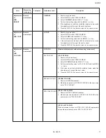
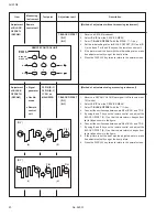
1) 1. IF
[1. VCO]

(a) 1 Key ......................................... Select 1. IF.
(b) 1 Key ......................................... Select 1. VCO. (CW)
(c) VCO(CW) TRANSF. .................. Adjust VCO(CW) while watching the colour (yellow/blue) of the characters on the screen.
(d) DISPLAY Key ............................ When this is pressed twice, you will return to the SERVICE MENU.

[2. DELAY POINT]

(a) 1 Key ......................................... Select 1. IF.
(b) 2 Key ......................................... Select 2. DELAY POINT.
(c) MENU 

 / 

+

 Key ......................... Adjust the setting value.

(d) DISPLAY Key ............................ When this is pressed twice, you will return to the SERVICE MENU.

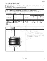
2) 2. V/C and 3. VSM PRESET

(a) 2 and 3 Keys ............................. Select 2. V/C and 3. VSM PRESET.
(b) MENU 

a

 key ........................ Select setting items.

(c) MENU 

 / 

+

 Key ......................... Adjust the setting values of the setting items.

Use the number keys on the remote control unit for setting of WHITE BALANCE and BLACK
OFFSET. For the setting, refer to each item concerned.

(d) DISPLAY Key ............................   When this is pressed, you will return to the SERVICE MENU.

(4) Release of SERVICE MENU

After completing the setting, return to the SERVICE MENU by pressing the DISPLAY key, then again press the DISPLAY key to return
to the normal screen.

Summary of Contents for AV-21F8

Page 1: ...4 OPERATING INSTRUCTIONS APPENDED 1 1 SPECIFIC SERVICE INSTRUCTIONS 4 SERVICE ADJUSTMENTS 10 STANDARD CIRCUIT DIAGRAM APPENDED 2 1 PARTS LIST 27 BASIC CHASSIS CL M AV 20N8 COPYRIGHT 2000 VICTOR COMPANY OF JAPAN LTD No 56030 Jul 2000 SERVICE MANUAL COLOUR TELEVISION AV 20N8 BK ...

Page 2: ... 32 0MHz 6 0MHz 32 5MHz 5 5MHz 33 5MHz 4 5MHz Colour Sub Carrier Frequency PAL 4 43MHz SECAM 4 40625MHz 4 25MHz NTSC 3 58MHz 4 43MHz Aerial Input Terminal 75Ω Unbalanced Power Input Rating AC110 240V 50 60Hz Operating AC90 260V 50 60Hz Power Consumption 110W Max 78W Avg Picture Tube Visible size 48cm measured diagonally High Voltage 26 5kV 1kV at zero beam current Speaker 5cm 12 cm Oval type 2 Aud...

Page 3: ...ical to those used in the original circuits Service should be performed by qualified personnel only 2 Alterations of the design or circuitry of the products should not be made Any design alterations or additions will void the manufacturer s warranty and will further relieve the manufac turer of responsibility for personal injury or property damage resulting therefrom 3 Many electrical and mechanic...

Page 4: ... other PW Board Before turning on power make sure that all connectors are prop erly connected WIRE CLAMPING AND CABLE TYING 1 Be sure to clamp the wire 2 Never remove the cable tie used for tying the wires together Should it be inadvertently removed be sure to tie the wires with a new cable tie FEATURES New chassis design enables use of an interactive on screen control Wide range voltage for AC po...

Page 5: ...AV 20N8 No 56030 5 6 2 2 2 A B C C CRT SOCKET PWB Within MAIN PWB MAIN PWB SPEAKER SPEAKER REAR COVER A2 PWB FRONT CABINET ...

Page 6: ... screen will be displayed See Fig 2 3 Check whether the setting values of the SYSTEM CON STANT SET are the same as those indicated in Table 1 If the value is different select the setting item with the MENU a key and set the correct value with the MENU key 4 Press the DISPLAY key twice to return to the normal screen 5 Receive channel setting Refer to the OPERATING INSTRUCTIONS and set the receive c...

Page 7: ...lume OFF TIMER OFF TV VIDEO TV AUTO SHUTOFF OFF ON SCREEN DISPLAY POSITION NUMBER DISPLAY ECO SENSOR OFF COLOUR SYSTEM PAL LANGUAGE THAI SOUND SYSTEM B G BLUE BACK OFF BILINGUAL MODE I ON TIMER PR1 0 00 PICTURE MODE VSM BRIGHT CHILD LOCK OFF LIVE SPATIAL OFF PICTURE BOOSTER OFF USER SETTING VALUES Table 2 Setting item Setting contents Setting value 1 INCH 21 2 COLOUR MULTI 3 VIDEO INPUT 1 4 ECO SE...

Page 8: ...3 BRIGHT 4 CONT 5 COLOUR 6 TINT TV VIDEO 7 BLACK OFFSET R Y B Y 8 SHARP 9 TEXT RGB CONT 10 H CENTER 11 V HEIGHT 12 V LIN 13 V S CR 14 V CENTER 15 AMP T SHARP SERVICE MENU SETTING ITEMS Table 3 Service menu Setting item 3 VSM PRESET TINT BRIGHT STD SOFT COLOUR BRIGHT CONT SHARP Do not adjust Do not adjust ...

Page 9: ...sistors diodes variable resistors etc 1 Apply extra solder to each lead 2 As shown in the figure while pushing the chip part with twee zers alternately melt the solder at its each lead Then shift and remove the chip part Note After removing the part remove remaining solder from the pattern REPLACEMENT OF CHIP COMPONENT 2 How to install Chip parts Resistors capacitors etc 1 Apply solder to the patt...

Page 10: ... the adjustment items of this service adjustment 7 Preparation for adjustment presetting Unless otherwise specified in the adjustment items preset the following functions with the remote control unit BASIC OPERATION IN SERVICE MENU 1 TOOL OF SERVICE MENU OPERATION Operate the SERVICE MENU with the remote control unit 2 SERVICE MENU ITEMS With the SERVICE MENU various settings adjustments can be ma...

Page 11: ...T SUB MENU SCREEN Fig 2 SERVICE MENU BRIGHT SUB MENU 3 VSM PRESET a SELECT OPERATE DISP EXIT BRIGHT STD SOFT Setting item TINT COLOUR BRIGHT CONT SHARP 1 VCO 2 DELAY POINT 1 2 SELECT DISP EXIT IF SUB MENU 1 IF VCO CW MHz TOO HIGH ABOVE REFERENCE BELOW REFERENCE TOO LOW DISP EXIT DELAY POINT AGC TAKE OVER OPERATE DISP EXIT Setting item 1 CUTOFF R G B 2 DRIVE R B 3 BRIGHT 4 CONT 5 COLOUR 6 TINT TV V...

Page 12: ...NU Key Adjust the setting value d DISPLAY Key When this is pressed twice you will return to the SERVICE MENU 2 2 V C and 3 VSM PRESET a 2 and 3 Keys Select 2 V C and 3 VSM PRESET b MENU a key Select setting items c MENU Key Adjust the setting values of the setting items Use the number keys on the remote control unit for setting of WHITE BALANCE and BLACK OFFSET For the setting refer to each item c...

Page 13: ...1 DEG T101 HVT UPPER FOCUS LOWER SCREEN REMOCON RECEIVER POWER ON TIMER ECO SENSOR VOL CH T FRONT MAIN PWB 1 Pin TP 91 B1 2 Pin NC 3 Pin X ray1 4 Pin X ray2 5 Pin TP E 1 5 TOP CRT SOCKET PWB SOLDER SIDE TP E E1 TP 47G T U CRT EARTH BRAIDED ASS Y A2 PWB CN001 IC201 CN001 T601 TOP 1 56 29 28 SIF DET IC601 IC602 ...

Page 14: ...s TOO HIGH displayed on the screen changes from blue to yellow Step 1 5 Then slowly turn the core of VCO CW TRANSF counterclock wise until the characters ABOVE REFERENCE changes from blue to yellow Step 2 6 Further slowly turn the core of VCO CW TRANSF until the colour of the characters BELOW REFERENCE changes from blue to yellow Step 3 7 Press the DISPLAY key three times to return to normal scree...

Page 15: ...the SERVICE MENU 3 Select 2 DELAY POINT by pressing the 2 key on the remote control 4 Adjust the MENU or key until video noise disappears 5 Press the DISPLAY key three times to return to the normal screen 6 Turn to other channels and make sure that there are no irregu larities V C VIDEO CHROMA CIRCUIT ADJUSTMENT The setting adjustment using the remote control unit is made on the basis of the initi...

Page 16: ...ingle horizontal line appears white 7 Turn the SCREEN VR to where the single horizontal line glows faintly 8 Press the 2 key to return to 1 CUTOFF screen 9 Press the DISPLAY key twice to return to the normal screen 1 Receive a black and white signal colour off 2 Select 2 V C from the SERVICE MENU 3 Select 2 DRIVE R B with MENU a key and set each value to initial setting value with 4 and 7 keys or ...

Page 17: ...U or key 5 If the contrast is not the best with the initial set value make fine adjustment until you get the best contrast 6 Press the DISPLAY key twice to return to the normal screen Method of adjustment without measuring instrument PAL COLOUR 1 Receive a PAL broadcast 2 Select 2 V C from the SERVICE MENU 3 Select 5 COLOUR with the MENU a key 4 Set the initial setting value for PAL COLOUR with th...

Page 18: ...U or key 5 Connect the oscilloscope between TP 47G and TP E 6 Adjust PAL COLOUR to set the value A in the figure to 7V W G SECAM COLOUR 1 Receive a SECAM full field colour bar signal 75 white 2 Set the initial setting value of SECAM COLOUR with the MENU or key 3 Adjust SECAM COLOUR to set the value A in the figure to 7V W G NTSC 3 58 COLOUR 1 Receive a NTSC 3 58 full field colour bar signal 75 whi...

Page 19: ...ke fine adjustment until you get the best tint 6 Press the DISPLAY key twice to return to the normal screen NTSC 4 43 COLOUR When adjustment is done for NTSC 3 58 TINT appropriate val ues are automatically set for NTSC 4 43 TINT Method of adjustment using measuring instrument NTSC 3 58 TINT 1 Receive a NTSC 3 58 colour bar signal full field colour bar 75 white 2 Select 2 V C from the SERVICE MENU ...

Page 20: ...y twice to return to the normal screen Method of adjustment using measuring instrument 1 Receive a SECAM COLOUR bar signal full field colour bar 75 white 2 Select 2 V C from the SERVICE MENU 3 Select 7 BLACK OFFSET with the a key 4 Connect the oscilloscope between pin 35 of IC 201 and TP E 5 By using 4 and 7 keys on the remote control unit adjust the BLACK OFFSET R Y so that the waveform changes f...

Page 21: ...on the kind of signals vertical frequency 50Hz 60Hz When adjusted in 50Hz mode 60Hz mode will be automatically set The setting adjustment using the remote control unit is made on the basis of the initial setting values The setting values which adjust the screen to the optimum condition can be different from the initial setting values SUB MENU 2 V C 10 H CENTER 14 V CENTER Initial setting value Set...

Page 22: ...orated remark ably perform the following steps 10 Receive a cross hatch signal 11 Select 13 V S CR with the MENU a key 12 Set the initial setting value of 13 V S CR with the MENU key 13 Select 12 V LIN with the MENU a key 14 Set the initial setting value of 12 V LIN with the MENU key 15 Adjust V S CR and V LIN so that the spaces of each line on TOP CENTER and BOTTOM become uniform 16 Make sure tha...

Page 23: ...SETTING VALUE COLOUR 15 b b b b b b b b b b SETTING VALUE BRIGHT 15 b b b b b b b b b b SETTING VALUE CONT 30 19 14 SETTING VALUE SHARP 20 b b b b b 15 SETTING VALUE Setting Values for SUB MENU 3 VSM PRESET BRIGHT SUB MENU 3 VSM PRESET a SELECT OPERATE DISP EXIT TINT COLOUR BRIGHT CONT SHARP A2 SIF DET ADJUSTMENT Measuring Item Test point Adjustment part instrument Adjustment Oscillo Audio Output ...

Page 24: ... green raster signal from the signal generator and turn the screen to green raster 5 Move the deflection yoke backward 6 Bring the long lug of the purity magnets on the short lug and position them horizontally Fig 2 7 Adjust the gap between two lugs so that the green raster will come into the center of the screen Fig 3 8 Move the deflection yoke forward and fix the position of the deflection yoke ...

Page 25: ...ta red blue 3 Using 6 pole convergence magnets overlap the magenta red blue and green lines in the center of the screen to turn them to white 4 Repeat 2 and 3 above and make best convergence DYNAMIC CONVERGENCE ADJUSTMENT 1 Move the deflection yoke up and down and overlap the lines in the periphery Fig 2 2 Move the deflection yoke left to right and overlap the lines in the periphery Fig 3 3 Repeat...

Page 26: ...ediately Indication by the LED Item ON TIMER LED flashing intervals Priority of detection Over current protection At 0 25 second intervals 1 CRT NECK protection At 0 5 second intervals 2 Note In case of the item is indicated Check item Over current protection CRT NECK protection Details of detection An over current on the low B line is detected Operation of CRT NECK protec tion circuit Method of d...

Page 27: ...AV 20N8 No 56030 38 CTH 0007 CRT AV20N8BK BK 3 VICTOR COMPANY OF JAPAN LIMITED TELEVISION RECEIVER DIVISION 1106 Heta Iwai city Ibaraki prefecture 306 0698 Japan ...

Reviews: