


F 9
0708
.GB
10
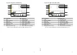
Faul localisation and identification
10.1
Fault localisation
A
If the fault cannot be eliminated, decommission the truck and inform the service de-
partment.
Fault
Possible cause
Remedial action
Truck does
not move
– Battery is still being
charged
– Key switch in vertical
position
– Battery charge to low
– Fuses defiective
– Disconnect 230 V or 24 V connection
– Push key and turn clockwise to the limit
and then pull out
– Check battery charge and charge batte-
ry, if necessary
– Check fuses F1 and F2
Load cannot
be lifted
– Truck is not operational
– Fuse defective
– Button “Lift load lifting
device” defective
– Perform all remedial actions listed under
“Truck does not move”
– Check fuse F1
– Check the button for correct functioning
according to the operating diagram
Load cannot
be lowered
– Button “Lower load lif-
ting device” defective
– Solenoid valve
defective
– Fuse defective
– Check the button for correct functioning
according to the operating diagram
– Check the solenoid valve for correct
functioning according to the operating
diagram
– Check fuse F1
F 9
0708
.GB
10
Faul localisation and identification
10.1
Fault localisation
A
If the fault cannot be eliminated, decommission the truck and inform the service de-
partment.
Fault
Possible cause
Remedial action
Truck does
not move
– Battery is still being
charged
– Key switch in vertical
position
– Battery charge to low
– Fuses defiective
– Disconnect 230 V or 24 V connection
– Push key and turn clockwise to the limit
and then pull out
– Check battery charge and charge batte-
ry, if necessary
– Check fuses F1 and F2
Load cannot
be lifted
– Truck is not operational
– Fuse defective
– Button “Lift load lifting
device” defective
– Perform all remedial actions listed under
“Truck does not move”
– Check fuse F1
– Check the button for correct functioning
according to the operating diagram
Load cannot
be lowered
– Button “Lower load lif-
ting device” defective
– Solenoid valve
defective
– Fuse defective
– Check the button for correct functioning
according to the operating diagram
– Check the solenoid valve for correct
functioning according to the operating
diagram
– Check fuse F1
Summary of Contents for EME 112
Page 1: ...Operating instructions 77800386 EME 112 G 05 00 07 08 ...
Page 3: ...0108 GB 0108 GB ...
Page 7: ...0506 GB 2 0506 GB 2 ...
Page 9: ...0600 GB A 2 0600 GB A 2 ...
Page 25: ...1001 GB D 6 1001 GB D 6 ...
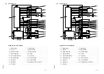
Page 28: ...E 3 0301 GB 5 2 1 4 3 6 7 8 9 10 E 3 0301 GB 5 2 1 4 3 6 7 8 9 10 ...
Page 35: ...0301 GB E 10 0301 GB E 10 ...
Page 47: ......
Page 65: ...0506 GB 18 0506 GB 18 ...