background image

Connecting the device 

picture 3 

Control cable: appropriate type, cross-section and routing for the specifications for 250 V 
cables. DALI and mains voltage wires can be run together in a cable, e.g. NYM 5x1.5 mm². 

DALI participants from some manufacturers have expanded functions and can e.g. be 
controlled via mains voltage on the DALI connection. When existing DALI installations are 
refitted, remove all corresponding operator controls. 

The DALI control voltage is a functional extra-low voltage (FELV). When performing 
installation, perform the installation in such a way that when an area is disconnected the 
lines carrying both the DALI and also the mains voltage are disconnected. 

Connect device as shown in the connection example (picture 3). 

Connect bus cable with connecting terminal. 

DALI devices can be connected to various phase conductors. 

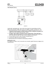
Installing the cover 

It is necessary to install a cover to protect the bus connection against hazardous voltages in the 
connection area. 

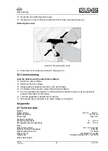
picture 4: Installing the cover 

5/8 

82559913 
J:0082559913 

16.08.2010 

DALI gateway 

Summary of Contents for 2097 REG HE

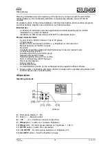
Page 1: ... integral part of the product and must remain with the end customer 2 Device components picture 1 1 Button field for manual control 2 Programming button and LEDs 3 KNX connection 4 DALI group display 5 Connection for mains supply 6 DALI output 3 Function System information This device is a product of the KNX system and complies with the KNX directives Detailed technical knowledge obtained in KNX t...

Page 2: ...straint Feedback of switching state and brightness value in bus and manual mode Central switching function Disabling function for each DALI group Separate ON and OFF delay Staircase lighting timer with run on time DALI commissioning with ETS plug in Short circuit protection Surge protection Overload protection An individual DALI device can be exchanged during operation without software i Delivery ...

Page 3: ...t operation it is not possible to control individual DALI devices i After 5 seconds without a button press the device returns automatically to bus operation Deactivating temporary manual control The device is in short term manual mode o No button press for 5 seconds or o Press c button briefly as many time as necessary until the device leaves the short time manual mode The display 4 is off Switchi...

Page 4: ...s blocked o Activate bus mode see section Deactivating permanent manual control i A blocked DALI group can be operated in manual mode Re enabling DALI groups The device is in continuous manual mode o Press c button briefly as many times as necessary until the display 4 flashes with the desired group o Press buttons ON n and OFF o simultaneously for at least 5 seconds Selected DALI group is enabled...

Page 5: ...s i The DALI control voltage is a functional extra low voltage FELV When performing installation perform the installation in such a way that when an area is disconnected the lines carrying both the DALI and also the mains voltage are disconnected o Connect device as shown in the connection example picture 3 o Connect bus cable with connecting terminal i DALI devices can be connected to various pha...

Page 6: ...e detailed information on commissioning of the DALI system see the technical product information for this device o Load the application software into the device i No programming is possible if no mains voltage is connected 6 Appendix 6 1 Technical data Supply Rated voltage AC 110 240 V Mains frequency 50 60 Hz Power loss max 3 W Ambient conditions Ambient temperature 5 45 C Storage transport tempe...

Page 7: ...evice has not been programmed Program device put DALI system into operation Individual DALI devices have no function Cause 1 Load is defective e g lamp Exchange load Cause 2 DALI device is defective Exchange defective device Switch on voltage Press c and ALL OFF buttons together for at least 10 seconds The device detects the exchanges DALI device and loads in the necessary data The display 4 shows...

Page 8: ... our central customer service office ALBRECHT JUNG GMBH CO KG Service Center Kupferstr 17 19 D 44532 Lünen Service Line 49 0 23 55 80 65 51 Telefax 49 0 23 55 80 61 89 mail vka jung de General equipment Service Line 49 0 23 55 80 65 55 Telefax 49 0 23 55 80 62 55 mail vkm jung de KNX equipment Service Line 49 0 23 55 80 65 56 Telefax 49 0 23 55 80 62 55 mail vkm jung de The Œ symbol is a free trad...

Reviews: