background image

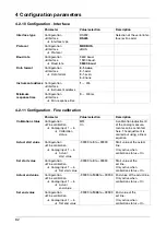
4 Configuration parameters

64

Summary of Contents for LOGOSCREEN 500

Page 1: ...Paperless recorder B 95 5015 Operating Instructions 04 02 00378469...

Page 2: ......

Page 3: ...2 5 2 Resetting the counters integrators timers 16 2 5 3 Behavior on instrument reconfiguration 17 2 6 Math logic module 18 2 7 Operating modes 21 2 8 Data storage 22 3 Operation and visualization 23...

Page 4: ...iguration Measurement storage 59 4 2 7 Configuration Outputs option 60 4 2 8 Configuration Operating functions 61 4 2 9 Configuration Texts 61 4 2 10 Configuration Interface 62 4 2 11 Configuration Fi...

Page 5: ...sories 78 8 Installation 79 8 1 Location and climatic conditions 79 8 2 Mounting in position 79 9 Electrical connection 81 9 1 Installation notes 81 9 2 Technical data 81 9 3 Connection diagram 82 10...

Page 6: ...Contents...

Page 7: ...cessary settings are described in this manual If any difficul ties should still arise during commissioning you are asked not to carry out any unauthorized manipulations on the unit You could endanger...

Page 8: ...mm and the optional PC evaluation pro gram PCA Interface Description B 95 5015 2 It provides information on the serial interfaces RS232 and RS485 which can be supplied as an extra Using the interface...

Page 9: ...sed where special care is required when handling electrostati cally sensitive components 1 3 2 Note signs H Note This sign is used where your special attention is drawn to a remark v Reference This si...

Page 10: ...nctions the text shown corresponds to the function which is currently active Program manager Screen text Texts displayed in the setup program are shown in italics Edit Instrument data Menu items Menu...

Page 11: ...ay off Status LED red is on continuously while an alarm is present Enter select menu item enter input Menu back to the basic menu1 Exit previous window cancel current action Menu dependent function ke...

Page 12: ...perated from eight keys Three of these have fixed functions the other five softkeys have menu dependent functions v Chapter 2 1 Display and controls Softkeys The softkey functions appear in the bottom...

Page 13: ...ror can be read out from the instrument info window v Chapter 3 7 Instrument info If the keys are inhibited a key flashes in this position Alarm If an alarm has occured e g out of limit the alarm bell...

Page 14: ...line can be controlled by using the parameter Parameters Diagram view Channel representation 2 3 Analog inputs Internal analog inputs The paperless recorder can be equipped with 3 or 6 analog inputs W...

Page 15: ...arm OR linkage of all high alarms Counter integrator alarm 1 6 Limit infringements of counter integrator channels instrument software version 133 03 xx or higher and extra code are required Counter in...

Page 16: ...stinguish between the appear ance and disappearance of the signal The external texts are configured on the instrument under Configuration Operating functions v Chapter 3 5 Event list Event operation T...

Page 17: ...lso enter a weighting for the integrators Weighting example flow measurement input signal from 0 20mA corresponds to 0 1000 l sec time base 1sec weighting 0 001 display of the integration value quanti...

Page 18: ...There is a reporting period for each counter integrator timer At the end of this period the current data value and time are stored and the value is reset to 0 Subsequently the next period can be reco...

Page 19: ...ata Code No Password Counter Int reset Reset via the Disk manager menu If the function Update diskette incl counters is executed in the Disk manager menu the counts will also be stored and reset v See...

Page 20: ...math module measurement inputs can be used to calculate new virtual channels There are no separate math channels for the calculated channels the existing analog channels 1 3 6 are used instead In conf...

Page 21: ...can still be integrated into the math module Available as fixed functions are difference ratio humidity moving average For the moving average it is necessary to enter the reference channel in most cas...

Page 22: ...counters integrators counter integr reset event operation and key inhibit for output to a relay and as count input for a counter The following variables are available for the formulae logic inputs lo...

Page 23: ...s entered in the diagram every 5 sec Normal operation Normal operation is active whenever event or timed operation is not active Timed operation For timed operation a period of time can be determined...

Page 24: ...ed separately for normal event and timed operation Recording format The data are recorded encoded in a proprietary format Recording duration The recording duration depends on various factors number of...

Page 25: ...ecorder by switching on the supply power ON the start logo company logo appears During the screen build up the recorder is initialized with the data of the last configuration H After the initializatio...

Page 26: ...instru ment branch out The following levels are available Visualization Parameters Configuration Event list Disk manager Instrument info The basic menu is displayed after pressing the Mkey1 1 not from...

Page 27: ...egrators extra code In this case the symbol for indicating the counts will appear below the softkey on the right the symbol for showing the event list is shifted to the counter display Evaluate stored...

Page 28: ...he D key Using the parameter Parameters Diagram view Signal type or the button it is possible to select whether in addition to the analog channels the event traces are also to be displayed The content...

Page 29: ...ossible to select which bargraph on which channel is to be indicated Scaling start of the selected channel Lower limit marker of the selected channel no display when alarm is off Upper limit marker no...

Page 30: ...ualization 28 3 2 4 Large digital display large measurement This display type is limited to the digital display 3 2 5 Curve representation header switched off This display type is limited to the repre...

Page 31: ...scrolled shifted on the screen within the measurement data that are stored in the internal memory H Measurement acquisition remains active during history representation Cursor violet Current zoom magn...

Page 32: ...easurement data on the screen is given as a ratio in steps 1 1 1 2 1 5 1 10 1 20 1 50 and 1 100 For instance 1 100 means that 1 screen pixel corresponds to 100 measure ments which signifies that only...

Page 33: ...nimum and one maximum value may be displayed graphically for one instant of time storage rate Using the key it is possible to switch between minimum and maximum value display within the display mode m...

Page 34: ...le the screen below for example appears after pressing the softkey which shows the current counts in numerical form Expanded representation is activated by pressing the softkey show curves expanded re...

Page 35: ...d indication Here mm h time div or storage rate is selected for the speed display in the diagram Example A diagram speed of 1h div corresponds to approx 22mm hr Display off Switch off event waiting ti...

Page 36: ...r perforations appear in the diagram thus giving the picture the appearance of a conventional chart recorder Counter integrator reset After the password has been successfully entered the counts for ea...

Page 37: ...nu led window technology Individual menu items can be selected in the win dows The window title describes the contents of the window When a menu item has been selected a further window is opened with...

Page 38: ...le texts are assigned to the events at the operating level Configuration v Chapter 4 Configuration parameters Freely definable texts 18 texts can be freely defined up to a length of 20 characters Stan...

Page 39: ...rance and disappearance of the signal Example Basic menu Event list The event list is called up via the basic menu Event list Standard text Supplementary text Entry in event list Logic input 2 ON Logi...

Page 40: ...The configuration data can be downloaded from and saved to diskette A con figuration can thus be copied from one instrument to another or it can be transferred from and to the PC setup program Basic m...

Page 41: ...uration parameters H The function Compl measurement data Disk serves to sal vage data when the original diskette is no longer available Residual capacity of diskette in percent Background flashes on e...

Page 42: ...there is no diskette in the instrument the diskette symbol flashes in the status line DISKETTE WRITEPROTECTED The inserted diskette cannot be written to because it is write protected Remedy Remove wri...

Page 43: ...s message appears when a capacitor is built into the recorder for memory buffering and the instrument has remained switched off for such a long time that the capacitor has become discharged Caution Th...

Page 44: ...lost A discharge of the battery storage capacitor occured during the last lengthy supply interruption The clock was set to 01 01 97 00 00 00 Remedy Reset the time v Chapter 4 2 2 Configuration Instru...

Page 45: ...ting by using E After the character to be altered has been selected and the switch made to character set matrix the cursor is positioned on the current character in the character set matrix Character...

Page 46: ...s 0 no password request If you enter a value unequal to 0 please take into account that this number must also be sent to the recorder by an attached communication program All passwords can be programm...

Page 47: ...Password request in the Configuration menu After the password has been entered in the Configuration menu an additional security query will appear You will only be able to access the parameters when yo...

Page 48: ...3 Operation and visualization 46...

Page 49: ...47 4 Configuration parameters 4 1 Operating example 1 if applicable the code number must also be entered here 2 cancel entry the old settings are retained 3 confirm entry...

Page 50: ...rage rate The selected display mode is shown in the diagram representation Switch off event Parameters Display off Switch off event Waiting time Operating signal The type of display switch off is sele...

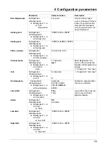
Page 51: ...ut Counter Int reset Parameters Counter Int reset Channel 1 6 999999999 0 999999999 The start value for the counter or integrator can be entered here The current value is not saved Count changes are d...

Page 52: ...if the changeover switch is set to User timed Summer time start time Configuration Instrument data Summer time Start time any time can only be configured if the changeover switch is set to User timed...

Page 53: ...menu 0000 off Code number Counter Int reset Configuration Instrument data Code No password Counter Int reset 0000 9200 9999 Code number to delete the individual counts 0000 off Code number RS232 RS48...

Page 54: ...K NiCrSi N Cu Con T PtRhPtRh B PtRh Pt R PtRh Pt S Cu Con U Fe Con L W3W25Re W5W26Re Connection circuit Configuration Analog inputs Analog input 1 6 Connection circuit 2 4 wire Cold junction Configur...

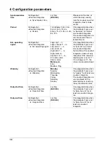
Page 55: ...racters Inp 1 Short designation It is shown in the channel line header with bargraph and scaling v Chapter 3 8 Text input Unit Configuration Analog inputs Analog input 1 6 Unit 5 characters v Chapter...

Page 56: ...ext Text 1 18 No text Alarm delay Configuration Analog inputs Analog input 1 6 Alarm Alarm delay 0 32767s Alarm delay is activated at a value of 0 When activated an alarm will only be generated when i...

Page 57: ...trace Trace designation Configuration Event traces Event traces 5 6 Trace designation 7 characters xxxx v Chapter 3 8 Text input Parameter Value selection Description Channel Configuration Counter Int...

Page 58: ...ter Int channs Channel 1 6 Weighting 99999 to 1 to 99999 Select the weighting factor here If for instance 0 001 is en tered a conversion from l sec to m sec can be achieved If a negative weighting fac...

Page 59: ...channs Channel 1 6 Decimal place Automatic X XXXX XX XXX XXX XX XXXX X XXXXX Specify the decimal place for displaying the count on the recorder screen Counter text Configuration Counter Integrator Cou...

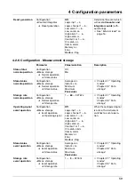
Page 60: ...Flag Only programmable when the parameter Type is set to external for at least one counter integrator Summation of the counter integrator values will only take place if the selected digital signal is...

Page 61: ...v Chapter 2 7 Operating modes Chapter 2 8 Data storage Storage rate normal operation Configuration Meas storage Normal operation Storage rate 1 60 32767s v Chapter 2 7 Operating modes Chapter 2 8 Data...

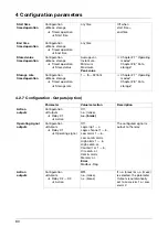
Page 62: ...uration Meas storage Timed operation Storage rate 1 5 32767s v Chapter 2 7 Operating modes Chapter 2 8 Data storage Parameter Value selection Description Action outputs Configuration Outputs Relay K1...

Page 63: ...8 No text v Chapter 3 5 Event list v Chapter 4 2 9 Configuration Texts External texts logic channel 1 6 Configuration Operating functions External texts Logic channel 1 6 Standard text Text 1 18 No te...

Page 64: ...n Fine calibration Analog input 1 6 Calibration status Off On A calibration adjustment of the analog measure ments can be activated here The adjustment is carried out using a linear equation Actual st...

Page 65: ...alibration Example A probe covers a temperature range from 200 to 300 C It has been fitted in a tunnel oven so unfavorably as to always indicate 10 C less than the temperature of the charge The incorr...

Page 66: ...4 Configuration parameters 64...

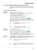
Page 67: ...ble for the easy configuration of the paperless recorder Hardware requirements PC 486DX 2 100 16 Mbyte RAM 15 Mbyte available on hard disk CD ROM 3 5 disk drive The program shows the current configura...

Page 68: ...s h Insert CD h Select Start Run h Input e g d start depending on drive h Click on OK The installation program will lead you through the rest of the installation with screen messages H If Microsoft Wi...

Page 69: ...ess recorder PC h Insert diskette into the recorder h Call up the Disk manager menu on the recorder h Select function Config data Diskette and activate h After a successful transfer the diskette can b...

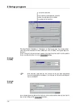
Page 70: ...Transfer the settings to the recorder using the Data transfer Data transfer to instrument menu or by activating the button Paperless recorder PC h Connect the setup cable to the serial interface of th...

Page 71: ...atics You can activate math channels in the setup program under Analog inputs or via Menu Edit analog inputs In the example below channel 3 is being used as math channel After carrying out steps 1 and...

Page 72: ...can either be direct or via a dialog Example humidity Example formula As as already been mentioned the formula can be entered either directly from the PC keys or by calling up the function 4 Function...

Page 73: ...h you will have to add the closing bracket yourself Example 1 add SQRT SQRT 2 add AE1 SQRT AE1 3 add SQRT AE1 Operator Explanation Example addition AE1 AE2 subtraction AE1 AE2 multiplication AE1 AE2 d...

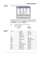
Page 74: ...c 0181 0229 052 4 0100 d 0182 0230 053 5 0101 e 0183 0231 054 6 0102 f 0184 0232 055 7 0103 g 0185 0233 056 8 0104 h 0186 0234 057 9 0105 i 0187 0235 058 0106 j 0188 0236 059 0107 k 0189 0237 060 010...

Page 75: ...e table Example The special character has to be input h Position the cursor with the mouse or by using the cursor keys on the insertion point of the character h Press the A key and hold it down h Ente...

Page 76: ...5 Setup program 74...

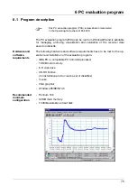
Page 77: ...and software requirements have to be met for the op eration and installation of the evaluation program IBM PC or compatible PC from 486 processor 16 MB main memory 3 5 disk drive CD ROM drive for inst...

Page 78: ...keys By means of the export filter it is possible to export the stored data CSV format for processing in different programs Excel Using the additional program Communication server the data can be rea...

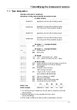
Page 79: ...x x x 22 20 53V AC DC 48 63Hz x x x x 23 110 240V 10 15 AC 48 63Hz 5 Extra codes x x x x 020 lithium battery for memory backup ex factory x x x x 021 storage capacitor for memory backup on request x...

Page 80: ...th foot can be released for strain relief of the connected sensor leads 7 3 Optional accessories setup program on CD ROM multilingual PC interface cable with TTL RS232 converter and adapter PC evaluat...

Page 81: ...c fields e g from motors transformers etc should be avoided The ambient temperature at the location can be between 0 and 45 C at a relative humidity of 75 no condensation v Chapter 9 1 Installation no...

Page 82: ...front into the panel cut out h From the back of the panel hook the two mounting brackets into the recesses on the sides of the housing The flat sides of the brackets must be against the housing h Pla...

Page 83: ...v Data Sheet T 95 5015 k Run the input output and supply cables separately not parallel to one another k All input and output cables that are not connected to the mains supply must be arranged as twi...

Page 84: ...ection must only be carried out by qualified per sonnel Terminals for screw clamp connectors 3 6 channel paperless recorder Connection symbol Analog inputs Connector Thermocouple 1 to 6 Resistance the...

Page 85: ...e data 3 TxD transmit data 5 GND ground RS485 9 pin SUB D 20 3 TxD RxD transmit receive data 5 GND ground 8 TxD RxD transmit receive data Relay outputs extra code Relay K1 K2 K3 changeover 30 31 32 Lo...

Page 86: ...9 Electrical connection 84 Setup interface The setup interface can be found on the left side of the housing seen from the front Setup plug...

Page 87: ...85 10 T V Report on Data Manipulation Security...

Page 88: ...10 T V Report on Data Manipulation Security 86...

Page 89: ...87 10 T V Report on Data Manipulation Security...

Page 90: ...10 T V Report on Data Manipulation Security 88...

Page 91: ...sentation 12 25 48 Character input 43 Character selection 43 Climatic conditions 79 Code No determined 51 Code number 35 38 44 51 Code number password 44 Cold junction 52 Color display 9 Commissioning...

Page 92: ...ber 51 Disk manager 38 Disk reserve 51 Display 9 Display and controls 9 E Electrostatic discharge ESD 5 Enable options code No determined 51 enable options 51 enabling code 52 Enabling code 52 End tem...

Page 93: ...67 Input signal 54 55 Input signal counter integrator 56 Installation notes 81 Instrument address 62 Instrument info 41 Instrument name 49 Instrument software 42 Integrator 15 55 Interface type 62 Int...

Page 94: ...ng signal outputs 60 61 Option enable Code No determined 51 Outline drawings 79 Outputs 14 60 61 action 60 operating signal 60 61 Overrange 12 P Panel fitting into 79 Paper perforations 49 Parameter s...

Page 95: ...emperature 52 Start time timed operation 60 Start value actual 62 set 62 Status line 11 Status message 40 Status LED 9 Storage rate 21 59 Store status 59 Stored value 21 59 Summer time 50 Supplementar...

Page 96: ...8 Type counter integrator 55 Type designation 77 U Underrange 12 Unit 53 Unit counter integrator 57 Unit of measurement variable 26 V Version number 42 W Waiting time 48 Warranty 5 Weekday counter int...

Page 97: ......

Page 98: ......

Page 99: ......

Page 100: ...Fax 49 661 60 03 6 07 E mail mail jumo net Internet www jumo net JUMO Instrument Co Ltd JUMO House Temple Bank Riverway Harlow Essex CM20 2TT UK Phone 44 12 79 63 55 33 Fax 44 12 79 63 52 62 E mail sa...

Reviews: