JUKI LH-4128 Instruction Manual Download Page 27

– 25 –

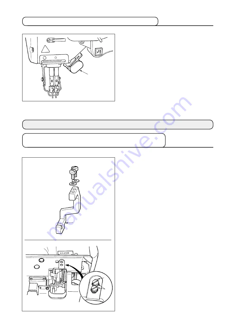
)  Prepare the gauge for bottom feed.

Temporarily set needle rocking rod fixing 

base 

1

 contaned n the accessores to hole 

2

 of the machne frame wth washers 

3

 and 

setscrews 

4

.

(1) How to use

)  Depress swtch 

1

, and the machne wll 

mmedately run n the reverse drecton.

2)  Reverse sttch s made as long as you keep 

depressng the swtch lever.

3)  Release the swtch lever for forwatd sewng.

5-6. One-touch reverse feed switch lever (for touch-back)

6. MAINTENANCE

6-1. Changing procedure to bottom feed and the adjustment  

(LH-4128 without thread trimmer only)

1

1

2

34

Summary of Contents for LH-4128

Page 1: ...ENGLISH LH 4128 4128 7 LH 4168 7 4188 7 INSTRUCTION MANUAL ...

Page 2: ...lease changeover when using the knee lifter 23 5 5 Separately driven needle changeover switch for LH 4168 7 and 4188 7 24 5 6 One touch reverse feed switch lever for touch back 25 6 MAINTENANCE 25 6 1 Changing procedure to bottom feed and the adjustment LH 4128 without thread trimmer only 25 6 2 Changing procedure to needle feed for LH 4128 only 27 6 3 Adjusting the inner hook guide 28 6 4 Needle ...

Page 3: ...4 to 25 4 mm Lift of presser foot 12 mm by knee lifter 5 5 mm by hand lifter lever 9 mm by knee lifter with wiper Lubrication New Defrix Oil No 1 Noise LH 4128 4128 7 Equivalent continuous emission sound pressure level LpA at the workstation A weighted value of 83 5 dB Includes KpA 2 5 dB according to ISO 10821 C 6 2 ISO 11204 GR2 at 4000 sti min Sound power level LWA A weighted value of 88 0 dB I...

Page 4: ...ad take up cover 3 Finger guard 4 Thread tension controller 5 Control box 6 Pedal 7 Knee lifter lever 8 Power switch 9 Hand switch 0 Operation panel 1 Bobbin winder 2 Thread stand 3 Oil supply opening 4 Reverse feed control lever 5 Hand lifter lever 2 3 4 8 6 7 5 0 1 9 1 4 3 2 5 ...

Page 5: ...on the front side A to the protruding section of the machine table using nails 2 Fix two machine head cushion seats 3 on hinge side B using a rubber based adhesive Then place bottom cover 4 on the fixed seats 3 Remove air vent cap 5 attached to the machine bed Be sure to attach cap 5 when transporting the machine head in the state that the machine head is removed from the machine table If the sewi...

Page 6: ...the AK device is not provided attach head support rod 9 to the machine table 6 7 9 6 Place urethane filter 0 on A Then put sheet metal fine mesh sheet type filter 1 on the urethane filter Place sheet metal fine mesh sheet type filter 2 on B Remove inlet port for circulation 3 fixed on the right hook driving shaft saddle Remove cap 4 from the end of the inlet port Then securely insert the inlet por...

Page 7: ...so as to prevent accidents caused by abrupt start of the sewing machine 1 2 3 3 4 Installation of thread stand Assemble the thread stand set it up on the machine table using the installation hole in the table and tighten nut 1 gently When you use power supplied by the overhead power line pass the power supply cord through hollow spool rest rod 2 1 3 5 Caution when installing the panel Use washers ...

Page 8: ...ll connectors have the inserting directions When using a type with lock insert the connectors until they go to the lock The sewing machine is not actuated unless the connectors are inserted properly In addition not only the problem of error warning or the like occurs but also the sewing machine and the control box are damaged 1 Pass the cords 1 of the thread trimming solenoid reverse stitching sol...

Page 9: ... 6 1 connect the cords below 1 Pass separately driven needle changeover switch cord 1 separately driven needle solenoid cord 2 and separately driven needle sensor cord 3 through hole A in the table to route them down under the machine table 2 Connect 10P connector 1 coming from the machine head to connector 4 CN125 3 Connect 8P connector 2 coming from the machine head to connector 5 CN129 4 Connec...

Page 10: ...dle 5 bundle detector cord connector CN30 above wire saddle 5 knee lifter detection sensor cord connector CN32 between wire saddles 5 and 6 and other cords to wire saddle 6 1 Fix the cord clamp and the cable clip band following the attaching procedure 2 When removing the connector remove it from the wire saddle and remove it while pressing the hook of the cable clip band 1 Fix all cables coming fr...

Page 11: ...hat fix it with the screw 2 7 Make sure that the power switch is turned OFF and insert power supply cord 1 coming from the power switch into the power plug socket Illustration is for the japanese specification 100V type 1 Top end of power supply cord varies in accordance with destination or supply voltage Check again the supply voltage and the voltage designated on the control box when installing ...

Page 12: ...sed 4 Confirm that LED goes out when knee pad plate 7 is released It is adjusted so that the knee lifting motion is detected when presser foot is lifted by 5 mm When using it with the lift amount of less than 5 mm reduce the standard adjustment value and re adjust according to step 3 5 When the magnet of knee lifter detection seat asm 4 comes near the detection section mark section of knee lifter ...

Page 13: ...he oil tank or proper lubrication will be not performed So be careful 3 When you operate the sewing machine refill oil if the top end of oil amount indicating rod 3 comes down to the lower engraved marker line of oil amount indicating window 2 WARNING 1 Do not connect the power plug until the lubrication has been completed so as to prevent accidents due to abrupt start of the sewing machine 2 To p...

Page 14: ... life of your machine be sure to periodically approximately once every three months clean up the above stated filter section urethane filter A circulation filter B plunger filter C and plunger filter 2 D When the filter is clogged lubrication trouble will occur and break down will be caused In addition when the oil becomes dirty replace the oil gathered in the oil tank 1 and the under cover Circul...

Page 15: ...ARNING Turn OFF the power before starting the work so as to prevent accidents caused by abrupt start of the sewing machine LH 4128 4128 7 Switch off the motor Use DPx5 needles 1 Turn the handwheel until the needle bar has come up to the highest point of its stroke 2 Loosen needle clamp screws 2 and pick up two needles 1 in the way that their grooves 3 are facing outwards 3 Insert the needles into ...

Page 16: ...and pull the thread so that it passes under the tension spring 3 Pass thread through another thread slit 2 then pass it through thread slit 3 on the bobbin case from the inside 4 Put the thread on bobbin threads slack preventer spring 4 WARNING Turn OFF the power before starting the work so as to prevent accidents caused by abrupt start of the sewing machine LH 4128 4128 7 LH 4168 7 4188 7 LH 4128...

Page 17: ...er of A to P Be careful of threading of needle clamp thread guides 4 O Figure A for thin filament thread of 60 or less Figure B for thick filament thread and polyester spun thread of 50 or more WARNING Turn OFF the power before starting the work so as to prevent accidents caused by abrupt start of the sewing machine Intermediate thread guide Fig A Fig B G type 1 L 2 M 3 N 4 K 0 O P A 1 2 B 5 4 3 D...

Page 18: ...ase pins 7 and 8 should not come in contact with disk release plate 9 In addition make sure that thread tension disks 1 and 2 securely rise when hand lifter lever 0 is turned in the direction of the arrow 4 9 Thread take up spring 1 When you want to change the stroke of the thread take up spring WARNING Turn OFF the power before starting the work so as to prevent accidents caused by abrupt start o...

Page 19: ...ase or to the left to reduce Turn stitch dial 1 counterclockwise clockwise to set the value on the dial corresponding to a desired stitch length to the marker dot 3 engraved on the machine arm When it is hard to turn stitch dial 1 turn it while slightly depressing reverse feed control lever 2 Reverse feed operation 1 Depress reverse feed control lever 2 2 Reverse stitches are made as long as you k...

Page 20: ...e bobbin thread on the upper part of the bobbin is excessive After the adjustment tighten the nut 6 7 To adjust the tension of the bobbin winder turn the thread tension nut 8 D E 7 7 7 6 8 1 Insert the bobbin deep into the bobbin winder spindle 1 until it will go no further 2 Pass the bobbin thread pulled out from the thread tension controller located on the right side of the thread stand as shown...

Page 21: ...e machine with screw 3 loosened Just loosen the screw and do not remove it 1 Stop position after thread trimming 1 The standard needle stop position is obtained by aligning marker dot A on the pulley cover with white marker dot B on the handwheel 2 Stop the needle in UP position turn OFF the power and loosen screw 3 to perform adjustment within the slot of the screw The needle stop timing is advan...

Page 22: ...urn the screw out 3 Adjusting the pedal stroke 1 The pedal stroke decreases when you insert connecting rod 5 into the left hole 3 Both depressing and returning of the pedal become heavy 4 13 Pedal pressure and pedal stroke 1 Installing the connecting rod 1 Move pedal 3 to the right or left as illustrated by the arrows so that motor control lever 1 and connecting rod 2 are straightened 2 Adjusting ...

Page 23: ...u reset the pedal to its neutral position during the automatic reverse feed stitching at seam start the machine stops after it cornpletes the reverse feed stitching The machine will perform normal thread trimming even if you depress the back part of the pedal immediately following high or low speed sewing The machine will completely perforrn thread trimming even if you reset the pedal to its neutr...

Page 24: ...e presser will rise by approximately 12 mm Do not perform thread trimming operation with the presser foot lifted since there is a case where the wiper comes in contact with the presser foot 5 2 Hand lifter Loosen nut 2 by turning counterclockwise and turn presser spring regulator 1 to adjust the pressure Turn the regulator clockwise to increase the pressure and turn it counterclockwise to decrease...

Page 25: ... the knee lifter When interlocking the thread tension release Remove the cap at the back pass screw 2 supplied as accessories through the hole in presser lifter plate 3 and fix it to presser lifter lever A 4 When interlocking the thread tension release 1 Thread slacks when turning cloth at the corner stitching and sewing trouble of thread tension release may occur 2 When the wiper is not used at t...

Page 26: ...and needle changeover switch and teaching switch Sew the corner in a single needle state lift the presser foot turn the cloth and sew the corner of return It is not necessary for the operator to perform the release at the time of return since the release of single needle after this work is automatically performed This function cannot be obtained unless the teaching switch is pressed Setting 1 Auto...

Page 27: ... How to use 1 Depress switch 1 and the machine will immediately run in the reverse direction 2 Reverse stitch is made as long as you keep depressing the switch lever 3 Release the switch lever for forwatd sewing 5 6 One touch reverse feed switch lever for touch back 6 MAINTENANCE 6 1 Changing procedure to bottom feed and the adjustment LH 4128 without thread trimmer only 1 1 2 34 ...

Page 28: ...with needle holes 8 in throat plate 9 and fix setscrews 4 which have been temporarily set 4 Loosen setscrews 2 2 places in sprocket 0 At this time remove the setscrew which is located in the same direction of engraved marker line 1 of the needle bar rocking rod Turn the pulley by 180 without turning the hook driving shaft 3 and align engraved marker dot 4 on hook driving shaft 3 with engraved mark...

Page 29: ...r LH 4128 only Loosen setscrew 2 in sprocket 0 turn the pulley by 180 align engraved marker dot 4 on hook driving shaft 3 with engraved marker line 1 and fix it with setscrew 2 Move the setscrew which is located in the same direction of the engraved marker line to the screw hole on the opposite side 2 3 0 4 1 5 1 6 7 5 1 Engraved marker line 7 6 8 Next adjust so that the needle comes to the center...

Page 30: ...d at the position of large engraved marker 4 the opening of the inner hook stopper is increased 4 3 2 1 WARNING Turn OFF the power switch and ascertain that the motor totally stopped before starting the work so as to prevent personal damage caused by abrupt start of the sewing machine LH 4128 4128 7 4168 7 LH 4188 7 LH 4188 7 1 Turn the handwheel in the normal direction until inner hook guide 1 ha...

Page 31: ...om the top end of the needle eyelet to the blade point of the hook is 1 2 mm The aforementioned adjustment is applied to the case when DPX5 needle is used When using DPX17 needle adjust with 5 C and 5 D respectively When loosening tightening setscrew 2 perform the work so that needle drive arm 3 does not move in the lateral direction When it moves needle bar torque or needle bar seizure will be ca...

Page 32: ...7 of the hook and needle 9 Then tighten setscrews 1 3 In the state described in step 1 4 align blade point 7 of the hook with the center of the needle and tighten setscrews 8 in the screw gear small 0 01 to 0 05 mm 8 0 1 1 9 7 7 9 Reference dimension Needle clamp height at needle bar lower dead point A A Throat plate installing plane Throat plate installing plane S F type G type LH 4128 4128 7 LH ...

Page 33: ...nd of the needle bar rocking base 2 2 mm up At this time the distance from the top end of the needle eyelet to the blade point of the hook becomes 1 2 mm 2 Determine the position of the hook 1 Loosen three setscrews 5 in the screw gear small 2 In this state loosen four setscrews 8 in hook driving shaft saddle 7 and move hook driving shaft saddle 7 to the right or left to adjust so that a clearance...

Page 34: ...ion where engraved marker dot C of feed bar arm aligns with engraved marker dot B of feed bar shaft Engraved marker dot A is for LH 3500 LH 4188 7 Engraved marker line is level 1mm Confirm the grounding when replacing the presser foot 1 When changing the height or the angle at the time of replacing the presser foot loosen needle bar connecting stud clamping screw 1 to adjust it Make sure of the cl...

Page 35: ...ring by moving rod 3 in the direction of arrow mark A and fix it with setscrew 4 Clamp trouble occurs even when the thread presser spring pressure is excessive or insufficient So be careful A 1 2 6 7 Move adjustment of the hook shaft saddle when replacing the gauge Move of the hook shaft saddle when replacing the gauge can be performed with ease by only loosening screws 1 and 2 It is not necessary...

Page 36: ...so that distance 2 between the top end of moving knife B at the time of waiting and the top end of counter knife 4 is dimension B Dimension B 4128 7 3 1 0 2 mm 4168 7 3 3 0 2 mm 4188 7 3 3 0 2 mm 3 Set clearance C between moving knife 3 and the inner hook to 0 4 0 1 mm when moving knife 3 works Loosen moving knife setscrews 6 and 7 and adjust the clearance 1 A 2 B 3 2 4 4 3 C 6 7 ...

Page 37: ... OFF the power switch and ascertain that the motor totally stopped before starting the work so as to prevent personal damage caused by abrupt start of the sewing machine When replacing the hook confirm the position of the needle guard The standard position is the state that hook needle guard 2 comes in contact with the side of needle 1 and the needle is along the hook needle guard by 0 to 0 1 mm I...

Page 38: ...of the 1 6 lines This means the number of stitches is 3 6 12 Stop of the needle bars and angle of corners for corners stitching for LH 4168 7 and 4188 7 1 Stop of the needle bars When separately driven needle changeover switch 1 is pressed during sewing the left hand needle bar stops and when 2 is pressed the right hand needle bar stops When the sewing machine is being operated at high speed the s...

Page 39: ... No E221 is displayed be sure to replenish grease to the specified place below call memory switch No 118 set the description to 1 and turn OFF the power 1 After replenishing grease call memory switch No 118 set the description to 1 and turn OFF the power Otherwise error No E220 or error No E221 is displayed again 2 For replenishing grease to the specified places below use JUKI GREASE A TUBE Part N...

Page 40: ...orresponding sections Do not loosen setscrews 7 in fulcrum shaft base 6 If it is removed once seizure of sewing machine torque will be caused 2 1 3 4 1 Replenishing grease to the needle bar drive cam section 1 Remove the top face cover and remove the rubber caps attached to the nipples 1 2 Fill joint 3 supplied as accessories with grease A from the grease tube 3 Connect pipe 2 with nipples 1 turn ...

Page 41: ...frame At this time be careful not to damage the needle bar If the needle bar is damaged wear of the needle bar can result 4 Fill the hole with grease A 5 Fit the cap back to its place If thread waste and dust accumulates inside the needle bar bushing a needle changeover error may result B A WARNING Turn OFF the power before starting the work so as to prevent accidents caused by abrupt start of the...

Page 42: ...70 4 6 3 1 2 3 1 9 1 6 80 3 8 2 6 1 9 1 6 90 3 2 2 2 1 6 100 2 7 1 8 Number of stitches Turning angle 1 2 3 4 5 6 7 8 9 40 4 9 3 9 3 3 2 8 2 5 2 2 50 5 1 3 8 3 1 2 6 2 2 1 9 1 7 60 4 1 3 1 2 5 2 1 1 8 1 5 70 5 1 3 4 2 5 2 0 1 7 1 5 80 4 3 2 8 2 1 1 7 1 4 90 3 6 2 4 1 8 1 4 100 3 0 2 0 1 5 Number of stitches Turning angle 1 2 3 4 5 6 7 8 9 40 4 4 3 7 3 2 2 8 2 5 50 4 3 3 4 2 9 2 5 2 2 1 9 60 4 6 3 ...

Page 43: ... 2 8 6 3 1 8 3 4 9 3 8 1 5 8 3 4 7 8 1 1 1 2 1 7 6 7 6 6 6 3 6 1 6 5 6 2 6 8 4 0 0 2 5 8 0 5 4 0 0 2 5 8 0 6 4 8 4 0 0 2 5 8 1 6 5 8 5 7 4 0 0 2 5 8 1 5 4 0 0 2 5 8 1 4 5 6 5 5 4 0 0 2 5 8 1 3 4 0 0 2 5 8 1 2 5 4 5 3 4 0 0 2 5 8 1 1 4 0 0 2 5 8 1 0 5 2 5 1 4 0 0 2 5 8 0 9 4 0 0 2 5 8 0 8 5 0 4 9 4 0 0 2 5 8 0 7 4 7 4 0 0 2 5 8 0 4 4 6 4 5 4 0 0 2 5 8 0 3 4 0 0 2 5 8 0 2 4 0 0 2 5 8 0 1 Ref No P a ...

Page 44: ... 4 8 7 5 7 1 0 1 4 8 8 5 6 1 0 1 4 8 9 5 5 1 0 1 4 9 0 5 2 1 0 1 4 9 1 5 1 1 0 1 4 9 2 5 0 1 0 1 4 9 3 5 9 6 1 6 2 6 3 6 4 6 5 6 6 6 7 6 8 6 9 7 0 7 1 7 2 7 3 7 4 7 5 7 6 7 7 7 8 7 9 8 0 4 0 0 3 5 8 9 6 2 0 m m 1 4 m m 2 2 6 2 5 1 0 7 2 2 6 2 5 3 0 5 2 2 6 2 5 4 0 4 2 2 6 2 5 5 0 3 2 2 6 2 5 6 0 2 2 2 6 2 5 7 0 1 1 4 0 9 m m 2 0 m m 2 3 P a r t N o 4 5 6 Ref No 1 m m 7 9 7 1 6 4 5 6 4 8 3 2 5 H 1 ...

Page 45: ...5 8 9 7 4 8 4 9 5 0 5 2 5 3 5 1 5 4 5 5 5 6 5 7 5 8 5 9 6 0 6 1 6 2 6 3 6 4 6 5 6 6 P a r t N o Ref No 4 0 0 6 1 2 7 0 4 0 0 6 1 2 7 1 4 0 0 6 1 2 7 2 4 0 0 6 1 2 7 3 4 0 0 6 1 2 7 4 4 0 0 6 1 2 7 5 4 0 0 6 1 2 7 6 4 0 0 6 1 2 7 7 4 0 0 6 1 2 7 8 4 0 0 6 1 2 7 9 4 0 0 6 1 2 8 0 4 0 0 6 1 2 8 1 4 0 0 6 1 2 8 2 4 0 0 6 1 2 8 3 4 0 0 6 1 2 8 4 1 9 7 8 7 9 8 0 8 1 8 2 8 3 8 4 8 5 8 6 8 7 8 8 8 9 9 0 9...

Page 46: ...B 1 8 3 2 5 8 4 0 0 3 5 8 7 7 7 0 4 0 0 3 5 8 7 8 4 0 0 3 5 8 9 7 4 3 4 4 4 5 4 6 4 7 4 8 4 9 5 0 5 1 5 2 5 3 5 4 5 5 5 6 5 7 P a r t N o 4 0 0 3 5 8 9 6 4 0 0 6 1 2 7 0 4 0 0 6 1 2 7 1 4 0 0 6 1 2 7 2 4 0 0 6 1 2 7 3 4 0 0 6 1 2 7 4 4 0 0 6 1 2 7 5 4 0 0 6 1 2 7 6 4 0 0 6 1 2 7 7 4 0 0 6 1 2 7 8 4 0 0 6 1 2 7 9 4 0 0 6 1 2 8 0 4 0 0 6 1 2 8 2 o N t r a P o N t r a P B 1 4 0 2 5 2 6 B A 0 A B 1 4 ...

Page 47: ...1 9 1 4 B1 4 0 2 5 26 BA 0 A B1 4 0 2 5 26 CA 0 A B1 4 0 2 5 26 DA L A 1 0 2 2 8 5 5 9 B1 4 0 2 5 26 FA L A B1 4 0 2 5 26 GA L A B1 4 0 2 5 26 HA L A B1 4 0 2 5 26 KA L A B1 4 0 2 5 26 LA L A 1 0 2 2 8 8 5 6 1 0 2 2 8 9 5 5 1 0 2 2 9 1 5 1 B 1 4 0 2 5 2 6 B A0 A B 1 4 0 2 5 2 6 C A0 A B 1 4 0 2 5 2 6 D AR A 1 0 2 2 8 5 6 7 B 1 4 0 2 5 2 6 F AR A B 1 4 0 2 5 2 6 G AR A B 1 4 0 2 5 2 6 H AR A B 1 4 ...

Page 48: ...onents on the bobbin winder TROUBLES 1 Thread breakage Thread is untwisted or scraped Needle thread 2 to 3 cm is left on the wrong side of the fabric 2 Stitch skipping 3 Loose stitch CAUSES 1 There is a sharp edge or burr on the thread path needle point hook blade point or bobbin case resting groove on the throat plate 2 Needle thread tension is too high 3 Bobbin case opening lever provides an exc...

Reviews: