JST CMK-R Operation Manual Download Page 24

JST


   CMK-R INDUSTRY STANDARD APPLICATOR


H:\0 - Quality Documents\2 Department\Tech Serv\Application tooling\Applicators and Die sets\TS142-01 

CMK-R Manual.doc 


24


999 


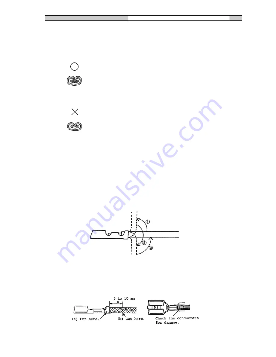
Checking for correct crimping: 
 
Following the items described below to check that the insulation barrel is correctly 
crimped. 
 
(1) Check that the wire insulation does not slip when the wire is bent in the order (1, 2  
      and 3) shown the right. 


(2) Cut off the insulation barrel at the (a) portion and cut off the wire at the (b)  
      portion. Remove the wire insulation and check the wire conductors for damage. 


Correct 
 
- The barrel edges firmly grip the insulation. 


Excessive crimping 
 
- The barrel edges cut into the strands. 


Summary of Contents for CMK-R

Page 1: ...H 0 Quality Documents 2 Department Tech Serv Application tooling Applicators and Die sets TS142 01 CMK R Manual doc CMK R INDUSTRY STANDARD APPLICATOR OPERATION MANUAL...

Page 2: ...when ordering spare parts All JST Industry standard Applicators have been designed to operate in Industry standard presses with a shut height of 135 78mm If you have any doubt to whether our applicato...

Page 3: ...ion 4 2 Shear Blade 5 3 Stripper 5 4 Upper Die Parts 6 5 Lower Die Parts 7 6 Alignment Of Shear Blade Anvil A and B 8 7 Guide Plates Feed Plate 9 8 Terminal Feed Pitch 10 9 Pressure Pad Adjustment 11...

Page 4: ...her is called a downstroke cam this operates in the opposite manner which means the terminal feeds forward as the press travels to bottom dead centre this type of cam is commonly used when the applica...

Page 5: ...oat freely and almost certainly cause punch damage 3 TERMINAL STRIPPER 3 1 PURPOSE After the terminal has been successfully crimped on the wire the terminal may adhere to the punches the stripper assu...

Page 6: ...ten them down with a 5mm hexagon screw and check that they are not clamped and do move up and down freely 4 Conductor punch 144 5 Insulation punch 145 6 A Spacer wire spring are sometimes fitted betwe...

Page 7: ...ust be fitted in the correct order as detailed below 1 Shear blade anvil A 2 Shear blade anvil B 3 Conductor anvil 4 Insulation anvil When all the above are in place using 2 x 5mm hexagon screws gentl...

Page 8: ...xagon screws that attach the Die block to the Die Plate Bring the Ram down slowly to align the Shear Blade with the slot in the Shear blade Anvil When the Shear blade passes through the slot in the Sh...

Page 9: ...ck and secure tightly using 2 x 5mm hexagon screws Next fit the Anvil parts as described in section 5 Now you can fit the 2 guide plates using 4 x 4mm hexagon screws do not tighten Take a strip of the...

Page 10: ...is nut is to achieve the correct pitch of the feed finger as shown in 8 3 not to set the final position over the Anvil 8 2 The pitch of the Feed Finger is adjusted by loosening the Stroke adjustment b...

Page 11: ...inal is in the correct position when crimped See section 16 10 2 To adjust the position of the Feed finger loosen the M5 screw in the lever block 124 then carefully loosen the Ring nut 125 Once these...

Page 12: ...rminal Holder Depending on which terminal you are processing a Terminal holder is sometimes fitted to the Shear blade Anvil A The purpose of this part is to stop the terminal from lifting up with the...

Page 13: ...positioned incorrectly 11 3 Springs Feed Finger Spring The function of the Feed Finger Spring is to keep downward pressure on the feed finger to ensure consistent feeding of the Terminal Return Spring...

Page 14: ...s recommended that you start with the higher letter H to avoid any damaged being caused by over crimping To ensure that you have the correct crimp height there is a silver label fixed to the side of t...

Page 15: ...09 142 Stripper bracket 4007 4017 112 Shank 4006 4010 143 Identification plate 4007 4018 113 Block ring MA01 225 114 Stroke adjustment plate 4007 4008 144 Conductor punch 115 Stroke adjustment shaft M...

Page 16: ...s and Die sets TS142 01 CMK R Manual doc 16 14 CMK R Applicator exploded view 156 151 152 153 154 105 104 106 133 130 117 114 116 118 134 144 137 139 132 143 115 120 122 129 131 125 158 146 112 108 11...

Page 17: ...re the lubrication Do not over grease the ram because the excess grease will either drip onto the tooling or will attract debris 1 5 Check that the dial settings are aligned correctly over the crimpin...

Page 18: ...e to the bearing surfaces of the ram feed cam and cam roller assembly and replace in the body of the applicator 2 9 Apply a few drops of light machine oil to each of the pivot points on the feed arm m...

Page 19: ...23 3 4 Tensile tests at the crimped section 25 4 Correctly Crimped Conditions 25 4 1 Crimped Appearance 25 4 2 The crimped cross section must be correctly finished as shown to the right 25 4 3 All co...

Page 20: ...be used are correct 1 Use stranded wire or cord Check the wire size and the insulation colour 2 Refer to the applicable wires in the catalogue to determine which terminal type is necessary to match th...

Page 21: ...Strip the shielding cable as shown below 3 Do not excessively twist the conductors 3 Crimping 3 1 Precautions regarding crimping At first glance crimping terminals appears to be very easy However cri...

Page 22: ...ays concentrate on what you are doing 6 Work in a stable posture 7 Do not place any unnecessary objects on the die unit 8 To make sure that the operating conditions are correct manually cycle the pres...

Page 23: ...lity in crimp height 2 After the dies are replaced or the crimp height is changed and before trial crimping rotate the manual handle to make sure that the dies do not interfere with each other Even wh...

Page 24: ...to check that the insulation barrel is correctly crimped 1 Check that the wire insulation does not slip when the wire is bent in the order 1 2 and 3 shown the right 2 Cut off the insulation barrel at...

Page 25: ...rmal crimping manner using a tensile tester or push pull gauge A simple method of suspending a predetermined weight can also be used Slowly pull the sample so that it receives no abrupt shock Example...

Page 26: ...rs and Die sets TS142 01 CMK R Manual doc 26 4 3 All conductors must be crimped Uncrimped conductors are not acceptable 4 4 The lance must not be deformed 4 5 The terminal tip and mating part must not...

Page 27: ...ctly bell mouthed The A portion of the barrel must be bell mouthed The B portion of the barrel is not necessarily to be bell mouthed The C portion must be free of cracks 4 8 The terminal must be cut a...

Page 28: ...mplete crimping The conductors protrude excessively The conductors interfere with the tightening nut preventing the terminal from being installed The wire insulation is crimped at the wire barrel Poor...

Page 29: ...s correct Insulation barrel Check that the crimped shape and the crimp Heights are correct Appearance Check that the wire barrel is correctly bell mouthed Check that the wire is crimped at the correct...

Page 30: ...rv Application tooling Applicators and Die sets TS142 01 CMK R Manual doc 30 Reference It is best to make up the Crimping CheckList as shown below for convenient Checking CRIMPING CHECK LIST Date Prod...

Reviews: