10-19
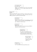
T2 NOISE TEST
DISABLED
Menu T2 forces the built-in self-diagnosis noise test to be executed and the
result is displayed in the NWW-82 Display Mode window.
Use + to change menu to ENABLED and then
Enter
to start the test and go to
next sub-level where the test result will be displayed.
T2.1 NOISE LEVEL
654 :: 732
Menu T2.1 shows the measured noise level in channel 1 to
the left and in channel 2 to the right.
Noise levels from an undisturbed log system shall show
values below 700 over time. Low values are better than high.
T3 TRU S BALANCE
DISABLED
Menu T3 forces the built-in self-diagnosis TRU signal balance test to be
executed and the result is displayed in the NWW-82 Display Mode window.
Use + to change menu to ENABLED and then
Enter
to start the test and go to
next sub-level where the test result will be displayed.
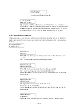
T3.1 SIG BALANCE
Q MAX= 78% OK
Menu T3.1 shows the measured signal balance as a quote
between the channels. Signal balances in the interval 50% -
200% are accepted as OK100% is the theoretically perfect
value.
Note!! If the ship doesn’t move the signal balance test might
indicate fail even if there is no problem with the signal
balance. Under such circumstances use the test with caution.
T4 LOOP TEST
DISABLED
Menu T4 forces the built-in self-diagnosis loop test to be executed and the
result is displayed in the NWW-82 Display Mode window.
Use + to change menu to ENABLED and then
Enter
to start the test and go to
next sub-level where the test result will be displayed.
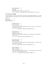
T4.1 LOOP TEST
0 : 82 : 0
The loop test generates transmit signals that are looped back
to the receiver and then correlated. Menu T4.1 shows the
correlation function at three different delays (lags).
The test is passed if the first and last value < 2 and the
Summary of Contents for JLN-900
Page 2: ......
Page 12: ...x This page is intentionally blank ...
Page 17: ...2 1 JLN 900 Technical Description ...
Page 23: ...2 7 sigbel ...
Page 30: ...2 14 This page is intentionally blank ...
Page 31: ...3 1 JLN 900 Technical Specification ...
Page 38: ...3 8 This page is intentionally blank ...
Page 39: ...4 1 JLN 900 Installation of Transducer and Bottom Parts ...
Page 59: ...4 21 Transducer and Valve Cover mounted Sea Valve fully opened ...
Page 63: ...4 25 Fig 1 3 Aligning Transducer Connecting Tube ...
Page 76: ...4 38 Mounting Sea Valve on Upper Flange DB ...
Page 81: ...4 43 Gasket Seal 2 ...
Page 83: ...4 45 Transducer and Valve Cover mounted Sea Valve fully opened ...
Page 86: ...4 48 Tube Bracket in its final position with Transducer flush seated ...
Page 88: ...4 50 Fig 2 5 Aligning Transducer Connecting Tube ...
Page 92: ...4 54 This page is intentionally blank ...
Page 93: ...5 1 JLN 900 Installation of NJC 80 Sig Processor ...
Page 150: ...6 50 This page is intentionally blank ...
Page 151: ...7 1 JLN 900 Display Technical Description ...
Page 167: ...7 17 No Name Default setting Function SD 4 2 SD 4 3 SD 4 4 there are remote systems connected ...
Page 179: ...8 1 JLN 900 Analog Display Technical Manual ...
Page 183: ...8 5 2 1 Main Dimensions NWW 828 Analog Display ...
Page 184: ...8 6 2 2 Dimmer Potentiometer connection Analog Display ...
Page 186: ...8 8 This page is intentionally blank ...
Page 187: ...9 1 JLN 900 Menu System ...
Page 208: ...9 22 This page is intentionally blank ...
Page 209: ...10 1 JLN 900 WATER TRACK Technical Manual including Menu system ...
Page 233: ...11 1 JLN 900 IEC 61162 NMEA 0183 User Guide ...
Page 254: ...11 22 This page is intentionally blank ...
Page 255: ...12 1 JLN 900 Harbour Acceptance Test ...
Page 266: ...12 12 This page is intentionally blank ...
Page 267: ...13 1 JLN 900 Calibration and Sea Acceptance Test ...
Page 280: ...13 14 This page is intentionally blank ...
Page 281: ...JLN 900 system drawings 14 1 ...
Page 289: ...CFT 780 4 TRANSDUCER 40m 14 9 ...
Page 290: ...NKF 980 Sea Valve 14 10 ...
Page 291: ...NKF 980 Sea Valve 14 11 ...
Page 292: ...NWW 82 MAIN DISPLAY 14 12 ...
Page 293: ...DISPLAY 3 1 87 14 13 ...
Page 294: ...NCM 1080 DIMMER UNIT 14 14 ...
Page 295: ...15 1 JLN 900 Description labels and drawings ...
Page 300: ...15 6 This page is intentionally blank ...
Page 301: ...16 1 Annex JLN 900 Speed Log System Manual ...
Page 302: ...16 2 Annex Table of contents ANNEX I EQUIPMENT RECYCLING 3 ANNEX II ENERGY SAVING 5 ...
Page 306: ...16 6 This page is intentionally blank ...
Page 307: ......


