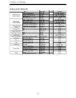
2.Installation of Scanner Unit > 2.1 Equipment Cable
2-10
2.1.5 Connection to the display-unit side terminal block
The terminal blocks of the junction box are pluggable type connectors. Connection
procedures are described below.
1) Use an attached lever or a flat-head screw driver, to press the control so
as to open the cable inlet.
2) Strip 8 to 9 mm of insulation off wire. Check the strip length and then insert
the wire until the end comes in contact.
3)
Release the tool from the terminal block and tighten the cable.
4) After the cable has been connected, gently tug at the cable to ensure that
it is securely fastened.
Terminal block connection method
Summary of Contents for JAN-7201
Page 2: ......
Page 24: ...xxii CWA 246 26inch Display Unit Mount Kit Warning Label ...
Page 25: ...xxiii CWA 245 19inch Display Unit Mount Kit Warning Label ...
Page 28: ...xxvi Warning Label NKE 1632 Radar Antenna Warning Label NKE 2632 2632 H Radar Antenna ...
Page 30: ...xxviii NTG 3230 Transmitter Receiver 30 kW ...
Page 33: ...xxxi CWA 245 Display Unit Mount Kit CWA 246 Display Unit Mount Kit ...
Page 76: ...2 Installation of Scanner Unit 2 2 Installation for the specified scanner model 2 13 ...
Page 78: ...2 Installation of Scanner Unit 2 2 Installation for the specified scanner model 2 15 ...
Page 80: ...2 Installation of Scanner Unit 2 2 Installation for the specified scanner model 2 17 ...
Page 82: ...2 Installation of Scanner Unit 2 2 Installation for the specified scanner model 2 19 ...
Page 84: ...2 Installation of Scanner Unit 2 2 Installation for the specified scanner model 2 21 ...
Page 86: ...2 Installation of Scanner Unit 2 2 Installation for the specified scanner model 2 23 ...
Page 88: ...2 Installation of Scanner Unit 2 2 Installation for the specified scanner model 2 25 ...
Page 90: ...2 Installation of Scanner Unit 2 2 Installation for the specified scanner model 2 27 ...
Page 92: ...2 Installation of Scanner Unit 2 3 Installation of Transmitter Receiver 2 29 ...
Page 94: ...2 Installation of Scanner Unit 2 3 Installation of Transmitter Receiver 2 31 ...


