


1.Overview > 1.2 Features
1-3
1.2
Features
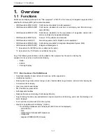
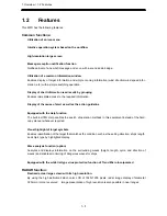
This MFD has the following features:
Common functions:
Utilization of an icon menu
Intuitive operation system based on the workflow
High-resolution large screen
Message reception notification function
Notifies arrival of a new AIS message and so on with a sound and a badge.
Utilization of a common information window
Enables display of target information and simple conning information (wind direction/wind speed infor-
mation, etc.) with a simple switching operation.
Display of chart information read results by grouping
Enables immediate access to the required information.
Display of the cause of alert as well as the action guideline
Equipped with the Help function
The built-in HTML Help enables the search of operation methods in this equipment instead of the hard-
copy manual whenever required.
Visual highlight of target symbols
Enables identification of the target that matches the condition such as the sailing direction, ship’s length,
and ship’s type by highlighted display.
Wave analysis function (option)
Analyzes and displays information on the surrounding waves (height, length, cycle, and direction of
waves) and enables monitoring of dangerous waves for ships.
Equipped with the white list type virus protection function of Trend Micro Incorporated
RADAR function:
Realized a clear large screen with its high resolution.
By using the high definition 26inch color LCD of 1920×1200 pixels, radar image display of diameter
320mm or more is secured. Image presentation of high resolution is also possible in near ranges.
Summary of Contents for JAN-7201
Page 2: ......
Page 24: ...xxii CWA 246 26inch Display Unit Mount Kit Warning Label ...
Page 25: ...xxiii CWA 245 19inch Display Unit Mount Kit Warning Label ...
Page 28: ...xxvi Warning Label NKE 1632 Radar Antenna Warning Label NKE 2632 2632 H Radar Antenna ...
Page 30: ...xxviii NTG 3230 Transmitter Receiver 30 kW ...
Page 33: ...xxxi CWA 245 Display Unit Mount Kit CWA 246 Display Unit Mount Kit ...
Page 76: ...2 Installation of Scanner Unit 2 2 Installation for the specified scanner model 2 13 ...
Page 78: ...2 Installation of Scanner Unit 2 2 Installation for the specified scanner model 2 15 ...
Page 80: ...2 Installation of Scanner Unit 2 2 Installation for the specified scanner model 2 17 ...
Page 82: ...2 Installation of Scanner Unit 2 2 Installation for the specified scanner model 2 19 ...
Page 84: ...2 Installation of Scanner Unit 2 2 Installation for the specified scanner model 2 21 ...
Page 86: ...2 Installation of Scanner Unit 2 2 Installation for the specified scanner model 2 23 ...
Page 88: ...2 Installation of Scanner Unit 2 2 Installation for the specified scanner model 2 25 ...
Page 90: ...2 Installation of Scanner Unit 2 2 Installation for the specified scanner model 2 27 ...
Page 92: ...2 Installation of Scanner Unit 2 3 Installation of Transmitter Receiver 2 29 ...
Page 94: ...2 Installation of Scanner Unit 2 3 Installation of Transmitter Receiver 2 31 ...


