JRC JAN-701B - Instruction Manual Download Page 364


5  Chart Editing 

5-38


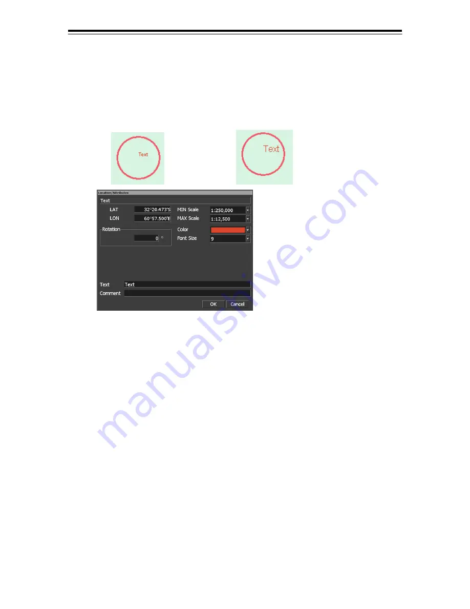
(6)   How to enter text (small/large font) 

1)   Select Small font or Large font on the text selection panel. 

•Be sure that the “cursor” column is displayed “Make Map”. 

2)  Move the cursor and left-click at the position you want to enter the text. 

Then, the “Location/Attributes” panel opens.    You can specify the location and select attributes 
by using this panel. 


(When you select Small Font) 

(When you select Large Font) 


[“Location/Attributes” panel for text] 

•  You can edit the latitude and longitude of each object by entering position latitude and 

longitude. 

•  You can edit the rotational angle of the text. 
•  You can set Min Scale and Max Scale that limit the display of this object. 
•  You can change the color (8 colors) and font size (6 to 72 points). 
•  You can enter the text that will be displayed on the chart and comment. 


3)  Left-click on the [OK] button to close the panel. 

The settings made in the “Location/Attributes” panel will be applied. 
Repeat above steps to enter text at desired locations. 

Summary of Contents for JAN-701B -

Page 1: ...JAN 701B 901B JAN 701B 901B INSTRUCTION INSTRUCTION MANUAL MANUAL ECDIS ECDIS...

Page 2: ......

Page 3: ...longer charged Extra protection is ensured by wearing dry cotton gloves at this time Another important precaution to observe is to keep one hand in your pocket at a time instead of using both hands a...

Page 4: ...sk someone to call doctor 4 Lay the patient on the back loosening the necktie clothes belts and so on 5 a Feel the patient s pulse b Check the heartbeat by bringing your ear close to the patient s hea...

Page 5: ...en take a deep breath and blow into the nostril through the pipe with the other nostril and the mouth completely closed 6 The patient may stand up abruptly upon recovering consciousness Keep the patie...

Page 6: ...ss the patient s body until it is depressed about 2 cm Repeat this about 50 times a minute Cardiac massage 2 If only one first aider is available perform a cardiac massage about 15 times and then give...

Page 7: ...tomate voyages For the best operation and performance results read this manual thoroughly before use Keep this manual in a convenient place for future reference Make use of this manual when experienci...

Page 8: ...is shown where any person is supposed to be injured or any property damage is supposed to occur if this indication is neglected and this equipment is not operated correctly Examples of pictorial indic...

Page 9: ...on under such condition may cause a fire an electric shock or a malfunction In case you find smoke strange smell or unusual heat coming from the equipment turn off the power immediately unplug the pow...

Page 10: ...se with the leg bearing and accidents may result Input the parameter accurately according to the specification of the ship Otherwise accidents may result After changing the setting execute to exit Nav...

Page 11: ...nformation automatically for navigation The positional information should always be checked by the user against such information from other sources Otherwise accidents may result Do not touch the equi...

Page 12: ...equipment in operation under such condition may cause a fire or a malfunction After turning off the power contact our head office or a nearby branch or local office to request servicing Edit routes in...

Page 13: ...d the function of Recovery Boot CD enough Don t continue the recovery as leave disk structure abnormal Otherwise a malfunction may occur This equipment is the system which is totally different from EC...

Page 14: ...xii Equipment Appearance Stand alone type JAN 701B...

Page 15: ...xiii Stand alone type JAN 901B...

Page 16: ...partment of Japan Coast Guard Chart Portfolio Software to manage the charts Imports and updates the charts C MAP Ed 2 C MAP Edition 2 A digital chart format by C MAP Norway C MAP Ed 3 C MAP Edition 3...

Page 17: ...layed on the screen Represented by one half of the length of the chart display screen RL Rhumb Line Rubber band Border that indicates the selected range S 57 IHO transfer standard for digital hydrogra...

Page 18: ...Base CD data has been imported USER CODE A user specific code assigned by JRC Required in using ARCS and S 63 charts UTC Universal Time Coordinated VRM Variable Range Markers WOL Wheel Over Line WOP W...

Page 19: ...2 1 7 CHART Information for ARCS 2 16 2 2 1 8 Tools Panel 2 17 2 2 1 9 Brilliance Setting Panel 2 18 2 2 2 Menu Title Bar 2 19 3 Basic Operation of ECDIS 3 1 3 1 Menu Operation 3 3 3 1 1 How to Select...

Page 20: ...3 60 3 5 1 Zooming Area Using the Rubber Band S 57 C MAP Only 3 60 3 5 2 Zooming In Out S 57 C MAP Only 3 61 3 5 3 Switching the Range S 57 C MAP Only 3 62 3 5 4 Switching the Scale S 57 C MAP Only 3...

Page 21: ...RM2 3 109 3 15 3 Operating EBL VRM Using the Display panel 3 110 3 15 3 1 Drawing and deletion EBL by the Display panel 3 111 3 15 3 2 Drawing and deletion VRM by the Display panel 3 111 3 15 3 3 Chan...

Page 22: ...onnected to a Printer 3 195 3 36 Saving the Screen 3 195 3 37 Displaying the Startup Menu Exit the navigation Planning 3 196 4 Route Planning 4 1 4 1 Route Planning 4 2 4 1 1 Setting the Route Options...

Page 23: ...ing Objects Only during the Manual Update Operation 5 40 6 Automatic Sailing 6 1 6 1 Automatic Sailing System 6 2 6 1 1 Change of Course Turning of Normal Route 6 2 6 1 2 Change of Course Turning of T...

Page 24: ...Data 8 6 9 Reference 9 1 9 1 Alarm Function 9 2 9 2 Chart Related Alarm Information 9 7 9 2 1 Alarm Information of ARCS Chart 9 7 9 2 2 Alarm Information of C MAP Ed 3 Chart 9 9 9 2 3 Alarm Informati...

Page 25: ...onning Display 12 2 12 1 2 Brightness Adjustment of Display Screen and Operation Panel 12 3 12 1 3 Adjustment of Alarm Volume 12 3 12 1 4 Operation of Software Keyboard 12 3 12 1 5 Turning Off the Pow...

Page 26: ...15 Specifications 15 1 15 1 Bridge Display Terminal 15 2 Index 1 END USER LICENSE AGREEMENT FOR JAN 701B 901B SERIES ECDIS SOFTWARE 3 Repair Request Form 5...

Page 27: ...1 1 1 Overview...

Page 28: ...electronic chart Superimpose display of radar echo on the electronic chart when ECDIS is used with the optional radar overlay kit True Relative motion display North up Course up display Display of ro...

Page 29: ...S Alarm functions Safety depth crossing alarm Dangerous areas crossing alarm Waypoint arrival alarm XTD alarm Logging functions Logging of navigation information onto the hard disk Own ship s playback...

Page 30: ...nings weather warnings and emergency messages from the connected Navtex receiver Ease of operation supported by high speed drawing and high speed processing Ease of user chart creation Multi view func...

Page 31: ...the main unit Operation Unit NCE 5163 E JAN 701B NCD 1444 1 Included in the main unit Processing Unit JAN 901B NCD 1445 1 Included in the main unit Instruction Manual Japanese 7ZPNA4055 1 Instruction...

Page 32: ...1 Overview 1 6 1 4 Construction The outline drawing of the unit is shown below Mass Approx 125 kg Cable Inlet Warning label NCD 2095 Bridge Display Terminal JAN 701B UNIT mm...

Page 33: ...1 Overview 1 7 ECDIS Mass Approx 150kg Cable Inlet Warning label NCD 2096 Bridge Display Terminal JAN 901B UNIT mm...

Page 34: ...1 Overview 1 8 MASS APPROX 85kg Flash mount type NCD 1444 T Processing Unit UNIT mm...

Page 35: ...1 Overview 1 9 ECDIS Flash mount type NWZ 173 ET 19 LCD Unit UNIT mm MASS APPROX 13 3kg...

Page 36: ...1 Overview 1 10 Flash mount type NWZ 170 ET 23 1 LCD UNIT UNIT mm MASS APPROX 25kg...

Page 37: ...1 Overview 1 11 ECDIS MASS APPROX 3 5kg NCE 5163 E Operation Panel...

Page 38: ...ew 1 12 1 5 System Configuration The following diagram shows an example system configuration connected with this equipment When ECDIS mode is used it displays navigation data received from the sensor...

Page 39: ...2 1 2 Names and Functions...

Page 40: ...1 Function of Operation Panel and LCD brilliance control 1 Function of operation panel Fig 2 1 and Fig 2 2 show the operation panel Table 2 1 describes the name and function of each part on the operat...

Page 41: ...he chart 15 AUTO SAIL 2 Starts Stops auto sail 16 MENU Display Menu title bar 17 AIS TT Selects AIS TT display 18 HOME Returns the own ship s position into the display 19 MOB MOB Man Over Board panel...

Page 42: ...it is installed 2 Effective only when the equipment is linked to auto pilot 2 LCD brilliance control The screen s brightness can be adjusted by using the brilliance control on the display panel By kee...

Page 43: ...ship s symbol and vector at the secondary position Head line Primary position track and time label Secondary position track EBL VRM markers RADAR echo Other ship symbols vectors and ship s track when...

Page 44: ...Estimated Time of Arrival at the To WPT ETA Speed to arrive at the to WPT by the planned time XTD XTD Cross Track Distance XTL XTL Cross Track Limit In XTD and XTL displayed side of P Port side and S...

Page 45: ...onfirmed Besides you can do acknowledge of the alarm and display of the alarm list See 3 3 7 The position of cursor Latitude Longitude Bearing and distance from cursor to own ship Own Ship Information...

Page 46: ...hanged In case of UTC display a time zone is displayed as 00 00 In case of LMT a set value is displayed in the time zone The following item can be changed setting in menu 7 Main 0 Setting 3 Date Time...

Page 47: ...or name of the display panel to the sensor setting by POSN1 POSN1 Sensor Setting Input data Display name on COG and SOG Display name on position DGPS1 GPS GPS GPS1 DGPS1 Differential GPS GPS DGPS1 DGP...

Page 48: ...by clicking this item While Association Setting is valid the background color of this item changes It does the detailed setting of Association Setting with menu MENU 1 AIS TT 0 Association Setting If...

Page 49: ...ing is displayed by TT1 input data when selecting MENU 1 AIS TT 1 TT1 TT1 REL TT1 GND TT1 SEA Blank is displayed when not selecting MENU 1 AIS TT 1 TT1 When using ground speed stability of Internal TT...

Page 50: ...clicking Route combo box a drop down list of route files is displayed First line File name Second line Comment of route file Note To use auto sailing feature the Auto Pilot equipment must be connected...

Page 51: ...estined waypoint Speed to arrive at the to destined waypoint by the planned time Displays speed to arrive at the destined waypoint by the estimated time of arrival Setting of estimated time of arrival...

Page 52: ...WPT Name of displayed WPT Longitude of displayed WPT Select from To Next To Displays To WPT Next Displays Next to To WPT Plan turn course radius order turn course radius is displayed Plan vessel speed...

Page 53: ...ith the drop down list button True Your ship moves on the chart When the ship reaches the predetermined limit on the screen the chart is automatically shifted to keep display the ship Relative Your sh...

Page 54: ...lly shifted to keep display the ship Relative Your ship stays at the center of the chart and the geographic objects move instead Free Chart is displayed regardless of the ship s movement Chart offset...

Page 55: ...ng position of cross point on EBL2 and VRM2 Base point mode switch button Blank CCRP mode D Dropped point mode Units of distance switch button When left click units of VRM distance is changed NM km sm...

Page 56: ...radar Changing 1 to 4 levels every Day Night level AIS Tracked Target brightness switch button Changing 0 to 4 level every Day Night level Day Night level switch button When left click display level...

Page 57: ...rack 1 Target Track Setting 3 3 9 3 2 File Operation 3 3 9 4 9 Own Ship s AIS Data 3 3 9 2 1 Message 1 Addressed Message 3 3 9 5 2 Broadcast Message 3 3 9 5 0 AIS Sentence 1 VDM 3 3 9 6 2 TTD1 3 3 9 6...

Page 58: ...8 2 3 Save Chart Setting 3 28 3 4 Chart Setting List 3 28 4 4 Select S 57 Chart 3 9 5 Fix View 3 7 3 6 Accept S 57 Updates 3 30 7 Graphical Index 3 31 8 Manual Update 5 4 1 Multi View 1 Single View 3...

Page 59: ...h Setting 3 24 2 7 PreSet Save 3 24 2 0 Option 3 24 2 9 Radar Overlay 1 Radar1 3 3 8 2 Radar2 3 3 8 3 Range Ring 3 3 8 4 Bearing Scale 3 3 8 0 Setting 7 11 1 Make AZ 3 23 2 File Manager 7 1 3 Test 1 A...

Page 60: ...tion Reference 1 Serviceman 1 Line Monitor 7 16 2 Adjust 7 17 3 Installation 1 Installation Information 7 18 2 CCRP Setting 7 15 2 4 Ship s Parameter 7 15 1 5 TCS Maintenance 7 19 6 Radar Initial Setu...

Page 61: ...5 Zoom Area 3 5 1 Dropped EBL VRM EBL1 VRM1 3 15 2 2 EBL2 VRM2 3 15 2 2 EBL1 3 15 2 3 EBL2 3 15 2 3 VRM1 3 15 2 4 VRM2 3 15 2 4 Move Origin1 3 15 2 5 Move Origin2 3 15 2 5 CCRP EBL VRM EBL1 VRM1 3 15...

Page 62: ......

Page 63: ...3 1 3 Basic Operation of ECDIS...

Page 64: ...ay panel and the menu names are written as xxxx in this book Example RADAR key on the operation panel MENU button on the display panel 1 Cursor menu name 2 Menu operation description The sequential op...

Page 65: ...the Trackball Trackball section on the operation panel Trackball The trackball is used to move the cursor on the screen for position designation selection of buttons on the display panel menu designa...

Page 66: ...te and Route Graphic mode Used to change objects and WPTs Box Cursor Indicates the position on the chart while in User Chart Edit Manual Update mode and Route Graphic mode Arrow Cursor Pointer Indicat...

Page 67: ...n Mark in that order The general menu selection procedure is as follows 1 Opening the menu entering Menu mode 2 Selecting the menu 3 Selecting the submenu options 1 Opening the menu For opening the me...

Page 68: ...Chart menu will open Step by step operation to select 6 Chart menu 1 Rotate the trackball to move the cursor to 6 Chart on the menu title bar 2 Left click the left button on the trackball section to s...

Page 69: ...u Then the Marking Highlighting submenu will open 2 Left click 2 Information Mark Then the Location Attribute panel will open How to Close the Panel Left click the OK or Cancel OK Enables settings in...

Page 70: ...to Use the context Menu You may use the context menu by pressing the right button by right clicking Example By right clicking on the chart display Right clicking the chart may open a context menu Lef...

Page 71: ...9 ECDIS Note In case of various operations which used the cursor the operation can be aborted by choosing Abort of the context menu Right clicking on the chart may open a shortcut menu Left click Abo...

Page 72: ...box You can enter numbers 1 First left click the entry box 2 Next enter the value 3 To fix the entry select other value entry box if any or the ENT key Drop down list 1 Left click the button to open...

Page 73: ...to turn it ON Other items are automatically tuned OFF The check mark shows the selected item Command buttons Left click the button to perform the button function List box You can select any item in t...

Page 74: ...the display or optional full key board 3 1 3 1 Use of the PS 2 Keyboard Note You cannot enter letters using the PS 2 keyboard in case an optional PS 2 keyboard is not installed 1 Loosen the 2 screws...

Page 75: ...keyboard By the column the kind of the keyboard is changes Numerical keyboard Left click to value entry box numerical keyboard is displayed See 3 1 3 3 Numerical Input Input a number Input latitude In...

Page 76: ...inus North South East West CLR Clear the inputted value and display default value ENT FIX the inputting data and close the software keyboard Close Clear the inputted value and returns to default value...

Page 77: ...3 Basic Operation of ECDIS 3 15 ECDIS 4 After inputting LAT left click the S bottom 5 Input ENT on software keyboard the software keyboard is closed and the input data is fixed...

Page 78: ...a is entered the data Close Clear the inputted text and close the software keyboard The text area is displayed default data The following button is changed to arrangement of software keyboard abc Inpu...

Page 79: ...igation Planning will be automatically displayed if is left clicked or no operation is conducted for 10 seconds Navigation Planning Screen Display panel Information display area Selects Route Selects...

Page 80: ...ifted by the offset function In this case return its color to gray See 3 34 4 Canceling the Ship Offset Alarms If an alarm occurs the alarm panel will blink in red and a sound will be heard Check the...

Page 81: ...l destination Arrived at LAST WPT alarm will occur After confirming the alarm contents press the ALARM ACK key on the operation panel or the Alarm Acknowledgement button on the display panel to stop t...

Page 82: ...the termination sequence described here Also how to recover the system in case of hung up is explained 3 3 1 Power ON POWER On the operation panel Press the POWER key The power turns on and the POWER...

Page 83: ...portfolio screen See Additional Manual for Chart Installation Chart Manager You can update the C Map chart Left clicking this menu will open the Chart Manager screen See Additional Manual for Chart In...

Page 84: ...el will not be displayed The Startup screen will be displayed instead Startup Screen Note ARCS will not be displayed unless a correct ARCS PIN is inputted on the ARCS PIN panel ARCS will not be displa...

Page 85: ...3 Basic Operation of ECDIS 3 23 ECDIS 2 After the Startup screen appears the Navigation Planning screen will be displayed after a short while Navigation Planning Screen Example...

Page 86: ...igation Planning gray screen will be displayed about 20 seconds but the power will eventually be turn off 3 3 5 Adjusting the Brightness and Sound Volume Perform the following adjustments as required...

Page 87: ...itch button 2 The operation panel brightness is changed by left clicking the panel brightness switch button Each time you left click the button The operation panel brightness changes 3 Brightness of t...

Page 88: ...panel brightness is changed in Target Symbol of Brilliance Tool area on display panel operation 1 The tool area is switched from Tools to Brilliance with tool area switch button 2 The panel brightness...

Page 89: ...onnection error and hardware error POSN 1 Data POSN1 shifted AC offline Operation Miss Specifying an unrelated place Exceeding the number of displays of AIS TT No Object Not Allowed AIS 95 Capacity Ke...

Page 90: ...Y2 Note When leaving for 3 seconds from the operation when operating from the darker one to the lighter one next key operation becomes operation from the lighter one to the darker one Menu operation 1...

Page 91: ...color is changed by Day Night level switch button Each time you press the key the display color changes The order which a display color switches over to is the same as the key operation Refer to Key o...

Page 92: ...m acknowledge button However until the cause of the alarm is removed in the alarm display area the alarm maintains a displayed condition Alarm List button displays the alarm record which occurred rece...

Page 93: ...problem which the alarm generated must be solved 2 If two or more alarms have occurred the display of the alarm acknowledge button and the display of the alarm display area is displaying alarm conten...

Page 94: ...on in the Alarm List also blinks After confirmation you can acknowledge the blinking alarm by left clicking the ACK button You can also open the Alarm List panel from the menu In the normal menu Selec...

Page 95: ...yet Icon stays in red The alarm is acknowledged but it is continuing Button changes to green when the alarm cause is removed Icon in green No alarm No Icon The alarm does not occur in the current syst...

Page 96: ...which needs to solve when occurring during navigation NAV alarm status is displaying dividing into the category below Safety contour Alarm Dangerous Alarm Route Monitoring Alarm Target Alarm LAT Limit...

Page 97: ...ast alarm lists see 3 26 Logbook Menu operation 1 In the normal menu Select MENU 7 Main 3 Test 1 Alarm Log in that order In the Table Editing menu Graphic Editing menu Select MENU 6 Main 3 Test 1 Alar...

Page 98: ...larm contents Detected Displaying date when the alarm occurred Acknowledge Displaying date when the alarm acknowledged Removed Displaying date when the alarm removed All Clear Erase all displays of th...

Page 99: ...n the normal menu Select MENU 7 Main 9 Radar Overlay 1 Radar 1 in that order In the Table Editing menu Graphic Editing menu User Chart Editing menu Select MENU 6 Main 9 Radar Overlay 1 Radar 1 in that...

Page 100: ...aring Scale the bearing scale display is turned ON and OFF When it is turned ON the mark is attached to the Bearing Scale The bearing scale will be superimposed on the chart 2 Radar Overlay Setting fr...

Page 101: ...e RAIN and SEA dials is more effective Normally keep this dial turned as far as possible to the left SEA Suppressing sea clutter The SEA dial lowers the reception sensitivity in near distances to redu...

Page 102: ...n sent from the radar currently selected will be superimposed on the chart 2 AIS TT display ON OFF from the menu TT 1 TT 2 AIS can be independently selected Selecting All can turns ON OFF TT 1 TT 2 AI...

Page 103: ...r In the Table Editing menu Graphic Editing menu User Chart Editing menu Select MENU 3 AIS TT 6 All List in that order The All List panel opens 2 Perform the following operation Left click one of the...

Page 104: ...se of the AIS TT target SOG Speed of the AIS TT target Position Position of the AIS TT target CPA Closest Point of Approach TCPA Time to Closest Point of Approach Status Status of the AIS TT target Vi...

Page 105: ...ishing 8 UNDER WAY SAILING Sailing 9 RESERVED FOR HSC High speed craft 10 RESERVED FOR WIG Wing in ground effect craft 15 NOT DEFINED Undefined Call Sign Call sign on the own station up to 7 character...

Page 106: ...UTION NO18 MOB 83 Ships according to Resolution No18 Mob 83 Vessels defined by the Radio Regulation 6X PASSENGER SHIPS Passenger ship 7X CARGO SHIPS Cargo ship 8X TANKER Tanker 9X OTHER TYPE OF SHIP O...

Page 107: ...e The AIS system equipped on own ship also has the own ship s AIS data to transmit for another ship Own ship s AIS data can be confirmed according to the following menu Select MENU 1 AIS TT 9 Own Ship...

Page 108: ...ting in that order In the Table Editing menu Graphic Editing menu User Chart Editing menu Select MENU 3 AIS TT 8 Target Track 1 Target Track Setting in that order Target Track Setting panel is display...

Page 109: ...the target and left click The following screen is displayed TT AIS ID of Target Track is displayed ID of AIS is displayed It is possible to change into the specified color In this regard however alrea...

Page 110: ...lid or invalid of the display of Target Track can be selected OFF When selecting OFF Target Track of selected number isn t displayed Target Track No 1 Target Track No10 Each number is changed to the c...

Page 111: ...possible to input of file name and save at this panel The file name is to the alphanumeric 10 character When there is same file name message to confirm overwrite is displayed Saved file name and date...

Page 112: ...ting and Deactivating AIS Targets The default for AIS targets is display in the inactive state The procedures below are used for activating and deactivating AIS targets Activating 1 Or right click on...

Page 113: ...n the normal menu Select MENU 1 AIS TT 5 Deactivate All AIS in that order In the Table Editing menu Graphic Editing menu User Chart Editing menu Select MENU 3 AIS TT 5 Deactivate All AIS in that order...

Page 114: ...that was selected first is displayed in the top panel As new targets are selected and displayed previous targets move down by one When the fourth target is selected the bottom target display panel wi...

Page 115: ...the Display panel It keeps pressing the MOB for three seconds or more In the operation panel It keeps pressing the MOB key for three seconds or more Then the MOB panel close and the MOB point symbol...

Page 116: ...change by the administrator setting Display Non display of MOB button on the Display Panel Display Non display of MOB information panel Switch of MOB Time TTG or Time MOB button is non displays it St...

Page 117: ...k drive and the DVD drive Note Do not remove a floppy disk from the floppy disk drive when the access lamp is on DVD drive Eject button Use to open and close the tray Access lamp Will light green when...

Page 118: ...f room to advance This function will be helpful if you have lost your ship on the chart Key operation 1 On the operation panel Press the HOME key Menu operation 1 On the display panel Left click the H...

Page 119: ...ting Motion Azimuth Mode True Motion 1 Rotate the trackball and move the cross cursor to the position you want to set it at the center of the chart 2 Left click at that position Moving to the Center o...

Page 120: ...hart with the Port List If a port is already registered you can switch to that chart The registered chart is displayed with the registered scale To return to the original chart where the ship is there...

Page 121: ...elete To close the panel left click the Close 3 4 5 Displaying the Chart by Entering the Position You can see the chart to the position you want by entering the position in the position entry panel Yo...

Page 122: ...2 Rotate the trackball to move the cursor to the top left of the area A you want to enlarge and left click there 3 Rotate the trackball to move the cursor to the bottom right of the area B you want to...

Page 123: ...P Only For scales see 3 5 4 Switching the Scale S 57 C MAP Only 2 Zooming in out using the display panel 1 On the display panel Left click the Zoom In or Zoom Out Each time you press the key the chart...

Page 124: ...range using the display panel 1 On the display panel Left click the range switching drop down list 2 Left click the range in the list The color of indicator left side of range switching drop down lis...

Page 125: ...1 Switching the scale using the display panel 1 On the display panel Left click the scale switching drop down list 2 Left click the scale in the list The chart is zoomed in or out according to the sc...

Page 126: ...tandard or Other on the display panel 1 Left click Object Category drop down list You can also use the menu to select an object category Also in the Standard and Other display methods you can specify...

Page 127: ...display example Note The display will be in gray without displaying a chart when a corresponding chart does not exist in the display area when a chart exists with only a part of data or when the displ...

Page 128: ...r example on the S 57 C MAP chart you cannot use the combination of True or Free mode and Course Up and WPT Up mode Also on the ARCS chart you cannot select Azimuth mode 1 Motion mode True Relative Fr...

Page 129: ...can readily be read out Course Up The chart automatically rotates so that the own ship always faces up on the display WPT Up The chart automatically rotates so that To WPT up on the display Rotation...

Page 130: ...where the ship does not exist is displayed by loading a new chart including by means of the Port List on the display panel From Relative mode to Free mode When the chart is scrolled When a chart is lo...

Page 131: ...ng it 3 7 2 Selecting Azimuth Mode You can select Azimuth mode using the display panel 1 Selecting Azimuth mode using the display panel 1 Left click the Azimuth drop down list on the display panel 2 S...

Page 132: ...Chart 5 Fix View in that order In the User Chart Editing menu Select MENU 4 Chart 5 Fix View in that order The chart display becomes fixed 2 Select Fix View in that order again to cancel Fix mode Exam...

Page 133: ...as it is to the My Port List with the current size So center the position you want before you register it to the My Port List When you want to select another chart Select right click Select Chart unde...

Page 134: ...he My Port List as follows 1 In the normal menu Select MENU 6 Chart 3 User Setting 2 My Port List in that order In the Table Editing menu Graphic Editing menu Select MENU 5 Chart 3 User Setting 2 My P...

Page 135: ...lect MENU 6 Chart 4 Select S 57 Chart in that order In the Table Editing menu Graphic Editing menu Select MENU 5 Chart 4 Select S 57 Chart in that order In the User Chart Editing menu Select MENU 4 Ch...

Page 136: ...e menu 3 10 1 Selecting Larger Smaller Chart ARCS Only In the ARCS chart you can select a larger or smaller chart using the display panel menu or the RANGE key on the operation panel On the operation...

Page 137: ...lect Chart panel 2 Left click the chart No you want and then left click the OK The panel closes and the selected chart is displayed on the screen If Preview is turned on a low resolution chart of the...

Page 138: ...button on the display panel The Select Chart panel opens 2 Left click the chart No you want and then left click the OK The panel closes and the selected chart is displayed on the screen If Preview is...

Page 139: ...lue square for each chart A selected chart will be displayed 1 Right click on the chart then select Change Active Panel from the context menu An available chart will be displayed as a blue square 2 Le...

Page 140: ...the screen 3 10 6 To Select the High Resolution Chart ARCS Only 1 Right click the cursor on the chart and select the High Resolution Area from the context menu by left clicking it Then the orange squa...

Page 141: ...m the context menu The Note and Diagram panel opens 2 When the desired items are selected the notes and diagrams for the corresponding chart are displayed The panel can be closed with the Close and th...

Page 142: ...ect MENU 4 Chart 4 ARCS 1 Temporary and Preliminary in that order The Temporary and Preliminary panel opens Depending on the chart used the items may not be displayed on the panel 2 Select the item yo...

Page 143: ...e Editing menu Graphic Editing menu Select MENU 5 Chart 4 ARCS 2 Adjust Datum Offset in that order In the User Chart Editing menu Select MENU 4 Chart 4 ARCS 2 Adjust Datum Offset in that order The Cha...

Page 144: ...nd position Then the offset values thus obtained are displayed on the Chart Shift panel You can edit the value Note that the cursor position is always displayed at the bottom of the display panel 3 Le...

Page 145: ...ds Enter the position into the value entry boxes Left click the Ship Position to enter the own ship s position Left click the by Cursor and left click the cursor at the position you want Then the posi...

Page 146: ...primary geodetic system is displayed in blue on the display panel and Chart Shift To WGS 84 is displayed in the screen message area In such a case the geodetic system conversion function will be deac...

Page 147: ...sections in which the same charts or different chart not different geodetic system can be displayed in various ways Also with the wide view function you can see the additional wide view screen in the...

Page 148: ...lower end title bar Right Left Chart is displayed dividing right and left View1 is displayed in right end title bar of chart and View2 is displayed in left end title bar Right Top View View2 is displ...

Page 149: ...Manual Update is reflected in View1 and View2 both As for the display panel one of the following the value of active View in View1 View2 is displayed Range Scale Motion mode Azimuth mode 3 11 2 Selec...

Page 150: ...en appears in the display panel area In the wide range view screen the currently displayed area is surrounded by the blue line If the same chart is displayed in multi view the view 1 chart area will b...

Page 151: ...s is UNLOAD Deleting the route To delete the route being selected from the chart left click the drop down list button to open the Route list and then left click UNLOAD The selected route is deleted fr...

Page 152: ...elect any waypoint manually select the waypoint 1 Left click the drop down list button to open the To WPT list 2 Left click any waypoint number For example when you start from the beginning of the sel...

Page 153: ...cted Way Point or Own Ship select the WPT number you want from the WPT No drop down list If you have selected Picked Point specify coordinates by left clicking an arbitrary point on the route 3 Left c...

Page 154: ...ion of ECDIS 3 92 Example use of Calculate Distance panel When selecting Way Point Select Way Point and an arbitrary WPT No The calculation result is displayed The route between the selected WPTs is s...

Page 155: ...point on the route The calculation result is displayed The route from the arbitrary point to WPT No 02 you have selected is shown in green Select WPT to go through The calculation result is displayed...

Page 156: ...ng menu the effectively of the XTD alarm can be changed 1 In normal menu Select 2 Route 4 Use XTD Alarm in that order The check in the menu switches over When a check is displayed the XTD alarm become...

Page 157: ...nu Select MENU 5 User Map 1 select User Map in that order The Open Chart File panel opens 2 Left click the user chart name you want and then left click the OK button The Open Chart File panel closes a...

Page 158: ...ill be the original chart S 57 C MAP ARCS 1 Reading out the object on the S 57 C MAP ARCS chart using the menu 1 Right click on the chart then select S 57 C MAP ARCS Information from the context menu...

Page 159: ...additional information the name of the additional information will be displayed in the combo box under the Information panel 1 Select the information name to be displayed then left click the Show 2 Th...

Page 160: ...the cross cursor changes to the box cursor 2 Rotate the trackball point the cursor to the object on the chart and left click the cursor Then the Location Attributes panel opens according to the selec...

Page 161: ...enter base point of the EBL VRM 1 Displaying and clearing the EBL1 VRM1 marker If you press the EBL1 or VRM1 key the EBL1 or VRM1 marker with your ship as the base point and the EBL1 VRM1 information...

Page 162: ...usly displayed For example let s assume that EBL1 and EBL2 are displayed on the screen and that EBL2 can be operated by the EBL dial In this case press the EBL1 key so that the EBL1 can be operated by...

Page 163: ...rker and EBL2 Marker Ship centered EBL VRM No displaying EBL Displaying EBL1 Displaying EBL2 Displaying EBL1 and EBL2 Displaying EBL1 and EBL2 EBL dial operate to EBL2 EBL dial operate to EBL1 EBL1 EB...

Page 164: ...ship s position to another position VRM1 EBL2 and VRM2 are operated in the same way as EBL1 1 With the EBL1 push EBL dial Then the EBL VRM base point displayed in the own ship position 2 Move the cur...

Page 165: ...peration should be carried out to set the base point of floating EBL VRM at the ship s center 1 Make sure that the base point of the displayed EBL1 is not fixed and floating The base point moves on th...

Page 166: ...both EBL and VRM drawing you can draw either 1 step method or 2 step step by step method In the 1 step method EBL and VRM appear at the same time In the 2 step method EBL appears and after fixing EBL...

Page 167: ...2 Step Step by step operation First EBL and then VRM Tips Useful context Abort During EBL VRM operation for example you can cancel the current operation step by the following procedure Right click at...

Page 168: ...text menu Then EBL1 is displayed and its base point is displayed on the cursor 2 Move the cursor and left click at the position you want Then the base point is fixed At the same time VRM1 is displayed...

Page 169: ...Click on the chart and select Dropped EBL VRM EBL1 from context menu Then EBL1 is displayed and its base point is displayed on the cursor 2 Move the cursor and left click at the position you want The...

Page 170: ...the position you want Then the base point is fixed 3 15 2 6 CCRP EBL VRM EBL1 VRM1 EBL2 VRM2 The following description is an operation to draw EBL1 VRM1 Drawing EBL2 VRM2 becomes a similar operation...

Page 171: ...BL1 Drawing EBL2 becomes a similar operation 1 Right Click on the chart and select CCRP EBL VRM EBL1 from context menu Then EBL1 is displayed and its base point is displayed on the ship At the same ti...

Page 172: ...dial Inactive Displaying OFF Displaying position of cross point on EBL1 and VRM1 Displaying position of cross point on EBL2 and VRM2 Base point button Blank CCRP D Dropped point Units of distance butt...

Page 173: ...click to this button Then EBL1 edit button is changed inactive and EBL1 disappears 3 15 3 2 Drawing and deletion VRM by the Display panel The following description is an operation of VRM1 VRM2 becomes...

Page 174: ...n Base point button is changed to display D and EBL1 is displayed At the same time the base point of EBL1 is displayed on the cursor 2 Move the cursor and left click at the position you want Then the...

Page 175: ...tting in that order The Marker Setting panel opens 1 Display Unit Simultaneity VRM1 distance unit VRM2 distance unit button of cursor synchronize when making Display Unit Simultaneity valid 2 EBL VRM...

Page 176: ...BL and VRM are displayed on the chart 2 Rotate the trackball to move the cursor and left click at the position to be fixed The bearing and distance are displayed at the fixed place on the chart As the...

Page 177: ...Dragging Anchor panel opens By default the heading forward position is displayed as the center of the circle Left clicking on the chart can also set the position as the center of the dragging anchor m...

Page 178: ...3 Basic Operation of ECDIS 3 116 Dragging anchor alarm When the Alarm list panel opens if a dragging anchor alarm occurs the Dragging anchor Icon blinks in red Red Icon Dragging Anchor...

Page 179: ...age you can put an Event Mark at the point where your ship is located 1 On the display panel Left click the Event Location Attributes Event Mark panel opens To check the Information on the Event Mark...

Page 180: ...lid without closing a panel 3 How to delete the Event Mark 1 In the normal menu Select MENU 6 Chart 1 Marking Highlighting 5 Delete Event Mark in that order In the Table Editing menu Graphic Editing m...

Page 181: ...position The left clicked position is displayed in the position box of the panel 3 In the Location Attributes Information panel perform the following editing operation Enter the comment on the Inform...

Page 182: ...left clicked position is displayed in the position box of the panel 3 In the Location Attributes Tidal Stream panel perform the following editing operation Set Drift Time setting Left click either Ac...

Page 183: ...anceled when clicking the OK when creating two points Diagram is canceled when clicking Abort from the context menu of the right click when creating two points Diagram is fixed when doing the left dou...

Page 184: ...out closing a panel For viewing the information on the Highlight or editing deleting the Highlight see 3 14 Reading Out Information on the Objects Note When entering data that requires detailed editin...

Page 185: ...en when the wheel is steered and when the ship begins to turn R Turning radius 1 In the normal menu Select MENU 7 Main 1 EBL Maneuver in that order In the Table Editing menu Graphic Editing menu Selec...

Page 186: ...bearing of the supplemental line The bearing of the supplemental line will be the bearing in which own ship will finally move The position of WOL will change depending upon the bearing of the supplem...

Page 187: ...Select MENU 6 Main 2 Cross Bearing in that order In the User Chart Editing menu Select MENU 5 Main 2 Cross Bearing in that order The Cross Bearing dialog box opens and the mouse cursor changes 2 Sets...

Page 188: ...ring the distance Setting range is 0 0NM 99 9NM 5 The drawing of the cross bearing line is determine by left clicking the Set and the bearing is displayed beside the cross bearing line 6 The cross bea...

Page 189: ...in that order In the Table Editing menu Graphic Editing menu Select MENU 6 Main 3 Create Clearing Line in that order In the User Chart Editing menu Select MENU 5 Main 3 Create Clearing Line in that o...

Page 190: ...n the chart screen Or value is input left clicking a column of Latitude Longitude Type Type of LOP is selected and the value is input Bearing Azimuth and distance are specified turns the EBL dial and...

Page 191: ...int panel is displayed when you left click this button When LOP or TPL is set 3 lines and more information message is displayed and cross point is displayed by select 2 lines Latitude Longuitude Displ...

Page 192: ...3 Basic Operation of ECDIS 3 130 1 Select Cross Point by 2lines LOP Displayed Select Cross Point panel and marked Cross Point chosen LOP becomes a red line Adjusted own ship s position...

Page 193: ...ECDIS 2 Select Cross Point by 3lines LOP Displayed information message Displayed Select Cross Point panel and no marked Cross Point Marked Cross Point chosen LOP red line Adjusted own ship s position...

Page 194: ...hat uses TPL 1 Display Create LOP panel The direction from the ship to the target is measured and LOP is set Moreover the distance to the ship and the target is measured and LOP is set Two LOP is set...

Page 195: ...ship is at some time 5 Display Create LOP panel The direction from the ship to the target is measured again and the third LOP is set Third LOP is set 6 Select Create TPL Then TPL is displayed accordin...

Page 196: ...ross point of TPL and the third LOP Information message displayed when there are three LOP or more Select OK Select the third LOP and TPL Displaying cross point 8 Reference Point button is selected an...

Page 197: ...rded in Logbook When Event Reference Point is selected from the list and View REF Point button is pushed the Information panel is displayed The Information panel displays Information of associated LOP...

Page 198: ...when left click onto the Acquisition Zone line Acquisition Zone 1 Setting of Acquisition Zone 1 is changed Start Side End Side Far Edge Width Acquisition Zone 1 Setting area Acquisition Zone 2 Setting...

Page 199: ...the operation panel is pushed short 4 EBL dial of the operation panel is turned and the angle of End Side is changed Similarly VRM dial of the operation panel is turned and the distance of Width is c...

Page 200: ...re represented by the indicators of the analog meter panel The color of the item and that of the indicator match each other So you can easily identify each indicator from the color COG Gray arrow Cour...

Page 201: ...thing except the analog meter Because the contents which can be displayed by the establishment environment are different for the details refer to the instruction manual of each of the facilities 1 To...

Page 202: ...the multi window condition In the normal menu Select MENU 7 Main 8 Multi Window 7 PreSet Save in that order It maintains the display condition and the display position of the present multi window When...

Page 203: ...thing except the crosshair cursor and leaving The selectable object and the displayed information When adjusting a cursor to each object for 1 second the following information is displayed Priority 1...

Page 204: ...s displayed when adjusting a cursor User Map Object Symbol Line Area Text MAP Comment Event Mark EVENT Comment Information Mark INFO Comment Tidal Stream Mark TIDE Comment 9 Highlight HIGHLIGHT Commen...

Page 205: ...3 26 2 Logbook Setting 1 In the normal menu Select MENU 7 Main 7 Logbook in that order The Logbook panel opens Contents of the logbook are as follows Note that to see all the contents scroll the pane...

Page 206: ...be reset to 0 0nm See 7 9 Clear Voyage Distance The voyage distance is available only if the interface with the ship speed sensor is in a log pulse format Some of the items of Logbook may not be avai...

Page 207: ...elected column and Up or Down The column changes the order in table of Logbook panel Column list is as follows Date Time Event POSN1 POSN2 Latitude Longitude COG SOG kn Heading Log kn Av Speed 4h kn A...

Page 208: ...the note become valid when making valid Navtex symbol becomes hidden when passing an Expire Date In case of invalid the symbol becomes hidden when passing on the 15 days from the date of receive In t...

Page 209: ...Navtex messages before the entered date time When the OK is left clicked the Navtex messages before the set date time are deleted All Message When the OK is left clicked All Message in the Logbook pa...

Page 210: ...ick this Then the position of recorded data is displayed at the center of the screen Print The Print panel will open You can print out the Logbook data after setting the printing conditions This is on...

Page 211: ...wing values and comment as required When the OK is left clicked the entered values are displayed in the Logbook panel The No in this panel corresponds to the No in the Logbook panel When clicking Canc...

Page 212: ...Log data is automatically saved according to the settings on the Logging area Also log data will be saved for displaying in the Logbook panel For example if you left click and select At Noon The log...

Page 213: ...be displayed on the chart according to the Navtex information Station You can filter the stations by specifying the first letter of the station name For example if you select the letter A the station...

Page 214: ...n Danger detection vector and sector Primary position track and time label etc Each item is shown in the following figure Own Ship s Setting Items 1 In the normal menu Select MENU 4 Ownship Track 0 Se...

Page 215: ...outline b the symbol a will be displayed unless enlarged chart is selected When the chart is enlarged the outline b will be displayed Your Ship Symbol 1 In the normal menu Select MENU 4 Ownship Track...

Page 216: ...Vector Display and Heading line 1 In the normal menu Select MENU 4 Ownship Track 0 Setting in that order The Own Ship Setting panel is displayed 2 Set each item on the Vector area To display the headi...

Page 217: ...suming that the ship sails at the current speed The sector and its radius can be set as required Danger Detection Vector and Sector 1 In the normal menu Select MENU 4 Ownship Track 0 Setting in that o...

Page 218: ...Left click the OK on the Alarm Limit Setting panel and then the OK on the Own Ship Setting panel to close all panels setting becomes valid Vector Turns ON OFF to affect danger detection vector Length...

Page 219: ...displayed 2 In the Track area left click Display Past Track and Display Time Label to select them 3 It enters value with the following item color Track Period Past POSN Interval Then left click the O...

Page 220: ...menu Select MENU 4 Ownship Track 0 Setting in that order The Own Ship Setting panel is displayed 2 Left click the item to select it Heading line Left click to turn it ON OFF Heading line Beam line Wh...

Page 221: ...in that order In the User Chart Editing menu Select MENU 4 Chart 0 Setting 1 S 57 C MAP ARCS in that order The Chart Setting panel opens This panel consists of three tabs View Common View1 and View2 e...

Page 222: ...MAP Only Base Standard Other Selection is the same as when the Base Standard and Other on the display panel are used For detailed function see 3 6 Changing the Object Category S 57 C MAP Only b Area...

Page 223: ...ion is effective only when the mode Course up is selected See 3 7 2 Selecting Azimuth Mode S 57 C MAP Only The chart will be turned step by step by the angle set here Namely if the Margin Chart Rotati...

Page 224: ...dingly Consider Scale Minimum When this item is selected if the chart is reduced exceeding the minimum scale set in a symbol the symbol will not be displayed The minimum scale of a symbol differs amon...

Page 225: ...on of ECDIS 3 163 ECDIS Full Light Line setting When Full Light Line is OFF When Full Light Line is ON Range of lighthouse light Range of lighthouse light The size of the circle changes according to t...

Page 226: ...peration of ECDIS 3 164 Consider Scale Minimum setting When the minimum scale of spot depth is 1 40000 and a chart display scale is 1 50000 When Consider Scale Minimum is ON When Consider Scale Minimu...

Page 227: ...two colors with Line of Shallow Contour and Safety Contour displayed as one color and and Line of Deep Contour displayed as another color Safety Depth is displayed at the value This feature is used to...

Page 228: ...66 Two Color Depth setting When Two Color Depth is OFF The sea is indicated in four colors When Two Color Depth is ON The sea is indicated in two colors Land Shallow Contour Safety Contour Safety Dept...

Page 229: ...3 Basic Operation of ECDIS 3 167 ECDIS Shallow Pattern setting When Shallow Pattern is ON Shallow Pattern is displayed When Shallow Pattern is OFF Shallow Pattern disappears Shallow Pattern...

Page 230: ...Shallow Pattern is OFF Isolated Danger in shallower water than safety contour does not display as mark f C MAP Ed 3 Database The chart that C MAP Ed 3 was imported can be chosen from g Chart Graphic...

Page 231: ...3 Basic Operation of ECDIS 3 169 ECDIS Fast Priority is given to drawing Speed Hi Quality Priority is given to drawing Accuracy...

Page 232: ...us Ways Multi View Wide View 1 Left click the setting items to set them ON OFF Left click the OK to close the panel Cancel It closes a panel without saving contents when clicking the Cancel Apply Cont...

Page 233: ...CS chart is displayed Note ARCS can be selected only if the ARCS chart has already been installed and the ARCS PIN is correctly inputted when the Navigation Planning is started ARCS and other S 57 or...

Page 234: ...Swept area Sand wave Tunnel Cable Submarine Navigation line Recommended track Ferry route Radar range Radar line Restricted area Ferry route Military practice area Offshore production area Caution ar...

Page 235: ...us zone Exclusive economic zone Radar station Radio station Coastguard station Rescue station Layers in C MAP Ed 3 S objects Land region Sea area named water area Causeway Dam Dyke Gate Dyke Slope top...

Page 236: ...bel for contour Water turbulence Tide Current non gravitational Seabed area Weed Kelp Spring Fishing facility Obstruction Wreck Underwater Awash rock Cable Submarine Pipeline Submarine on land Contine...

Page 237: ...ding so on Light description Note on chart data or nautical publication Geographic names National language Note When setting National Language in the validity it overlap with the other displaying info...

Page 238: ...function see 3 11 Displaying Chart in Various Ways Multi View Wide View 1 Left click the setting items to set them ON OFF Left click the OK on the panel to close the panel Cancel It closes a panel wi...

Page 239: ...ht Top view 3 28 2 Other Chart Setting 1 In the normal menu Select MENU 6 Chart 0 Setting 2 Other Charts in that order In the Table Editing menu Graphic Editing menu Select MENU 5 Chart 0 Setting 2 Ot...

Page 240: ...ng 3 Save Chart Setting 2 Save Chart Setting panel is displayed Name can be entered to 15 characters Select MENU 6 Chart 3 User Setting 4 Chart Setting List the saving setting can be loaded see 3 28 4...

Page 241: ...he set value which saved in Save Chart Setting 1 In the normal menu Select MENU 6 Chart 3 User Setting 4 Chart Setting List 2 Chart panel and a saving setting list are displayed Load Selected setting...

Page 242: ...t Abbreviations Displays a table of the meanings of the chart abbreviations 1 In the normal menu Select MENU 6 Chart 3 Chart Abbreviation in that order An Information panel with a table of the meaning...

Page 243: ...tting For Chart Portfolio operation see attached Chart Portfolio 1 Be sure that the SENC information level is set to Standard or Other A part is displayed in Base 2 In the normal menu Select MENU 6 Ch...

Page 244: ...d on the chart The objects of the updating chart will be superimposed on the original chart and show in red 4 Left click the OK The panel closes and the updating objects are merged with the original c...

Page 245: ...tem 1 In the normal menu Select MENU and then 6 Chart 7 Graphical Index in that order Then chart index is displayed on the chart and Graphical Index panel is displayed 2 Left click on the chart the Gr...

Page 246: ...condition Display ENC Data Switch Display ENC Data in Graphical Index Display Chart Name Switch Display the Chart Name If this function is effective Chart Name is displayed upper right in the chart in...

Page 247: ...pendant View in that order Date dependent View Setting panel opens 2 Enter the date time you want to display S57 63 charts And Left click the Apply button 3 The chart is displayed based on entered dat...

Page 248: ...For details on each setting item refer to the INSTRUCTION MANUAL for Radar being used The Rader Option panel will not be displayed if an optional radar board is not installed IR Interference Rejection...

Page 249: ...h setting range CPA Closest Point of Approach is distance between own ship and target CPA Limit setting range 0 1 9 9NM TCPA Time to Closest Point of Approach is time to own ship and CPA of target TCP...

Page 250: ...3 AIS Filter High Priority filter for display Ring The AIS targets within the specified distance are displayed It changes to edit mode when left click onto the Ring line Sector The AIS targets within...

Page 251: ...Number sequence It sets the range of Ring Minimum 0 0 NM Maximum 120 0 NM MAX It becomes valid when check is ON Range which was set in Ring and Sector is displayed when putting a check Filter Mode OF...

Page 252: ...ble Cross Line Red blink Initial acquisition mark Selectable AIS symbols Item Symbol Color Sleeping target Selectable Activated target Selectable Selected target Selectable Dangerous target Red blink...

Page 253: ...sel of 0 to less than 14 knots 60 sec Vessel of 0 to less than 14 knots and it is now changing the course 60 sec Vessel of 14 to less than 23 knots 36 sec Vessel of 14 to less than 23 knots and it is...

Page 254: ...information on originally the same ship is shown 1 In the normal menu Select MENU 1 AIS TT 0 Association Setting in that order In the Table Editing menu Graphic Editing menu Select MENU 3 AIS TT 0 Ass...

Page 255: ...tion is valid to 125 of the set value Association Target can be set in valid or invalid It becomes valid when putting a check It is connected with the Association of the display panel Synchronized wit...

Page 256: ...ition designated by left clicking the cursor Select to Cursor Shifts by entering the latitude longitude Select to Cursor Shifts by entering the offset value Select to Enter Offset When shifting the ow...

Page 257: ...in which the reference point mark is displayed Source Selects the type of reference positioning data that is to be displayed for Reference Point Mark GPS DGPS Decca Loran Radar Astronomical MFDF Tran...

Page 258: ...nel is colored in sky blue and the message Position Shift alarm is displayed in the message display area Check these indications and cancel the offset function if necessary 3 35 1 Shifting Using the C...

Page 259: ...Offset in that order 3 35 3 Shifting by Entering the Offset Value 1 In the normal menu Select MENU 4 Ownship Track 1 Adjust 3 Enter Offset in that order The Enter Offset panel opens 2 Enter the amount...

Page 260: ...displayed screen can be saved on the hard disk as a 256 color bit map file 1 In the normal menu Select MENU 7 Main 6 Save Screen in that order In the Table Editing menu Graphic Editing menu Select ME...

Page 261: ...ation Planning is exited the Startup Menu panel will be displayed For the Startup Menu panel see 3 3 2 Selecting the Startup Menu 1 In the normal menu Select MENU 0 Exit in that order The Confirmation...

Page 262: ......

Page 263: ...4 1 4 Route Planning...

Page 264: ...n the chart during editing Route planning using the Graphic Editor You can make a route by graphically drawing each WPT on the chart Editing Screen and Editing Menu When you enter the Table Editing mo...

Page 265: ...e Screen Note For each default value see 4 1 1 Setting the Route Options W000 Planned course W001 Planned speed kt Leg Port side in red line and port side width Starboard side in green line and starbo...

Page 266: ...ing in that order In the Graphic Editing menu Select Menu 4 Route 0 Setting in that order Then the Route Plan Setting panel opens 2 Select an item and enter the value in the numeric input box as neede...

Page 267: ...the arrival time is displayed at WPT during route monitoring When Estimated Time of Arrival is off no checkmark When Estimated Time of Arrival is on with a checkmark and UTC is selected for Route Moni...

Page 268: ...or more a GC leg exceeding 60 can be input Waypoints are added at intersections between the GC leg and 60 so a leg exceeding 60 is not input e Check Safety in Editing During editing the route safety...

Page 269: ...file Note In editing the route View Ship s Parameter can be displayed View Ship s Parameter dialog is only a display In Route Editing menu Table Graphic Select 4 Route 5 View Ship s Parameter in that...

Page 270: ...world geodetic system WGS 84 Use of routes edited with any other geodetic systems may cause accidents 4 1 2 1 Table Editing Mode On the operation panel Press the ROUTE PLAN key In the normal menu Sel...

Page 271: ...le Editing Menu Tree Main Menu Submenu Submenu Option Reference 1 File 1 New 4 1 2 4 2 Open 4 1 2 5 3 Import 1 Normal 4 1 2 6 2 TCS 4 1 2 6 3 2G TCS 4 1 2 6 4 Save 4 1 2 4 5 Save as 4 1 2 5 6 Export 4...

Page 272: ...3 10 9 2 Adjust Datum Offset 3 10 10 3 Datum Transformation 3 10 10 0 Setting 1 S 57 C MAP ARCS 3 28 1 2 Other Chart 3 28 2 6 Main 1 Maneuver Curve Remove Maneuver Curve 3 19 2 Cross Bearing 3 20 3 C...

Page 273: ...VRM1 3 15 2 2 EBL2 VRM2 3 15 2 2 EBL1 3 15 2 3 EBL2 3 15 2 3 VRM1 3 15 2 4 VRM2 3 15 2 4 Move Origin1 3 15 2 5 Move Origin2 3 15 2 5 CCRP EBL VRM EBL1 VRM1 3 15 2 6 EBL2 VRM2 3 15 2 6 EBL1 3 15 2 7 EB...

Page 274: ...urn RAD Time Zone Left click when checking the safety of the route As a result of the checking warning dialog box will appear if the route is not safety Left click to check if the route exceeds the li...

Page 275: ...ontext menu is displayed Operation is applied to the line which displayed a menu Left click when inserting a new WPT Left click when deleting a WPT Left click to divide the leg Left click to set defau...

Page 276: ...wchart for planning a route using the Table Editor File opening and saving operation differs depending on whether you make a new route file or you select a route file previously made though the table...

Page 277: ...diting operation Left click Save Left click Close End Left click Save as in the menu Enter the new file name To save without chang ing the file name When you want to change the file name Exits the Tab...

Page 278: ...n 2 Entering the Table Editing mode 1 On the operation panel Press the ROUTE PLAN key In the normal menu Select MENU 2 Route 1 Route Planning 1 Table Editor in that order Then the Table Editing screen...

Page 279: ...Ship s speed Sail RL GC Sail RL Rhumb line GC Great circle ROT min The ship s rotation over every 1 minute This item is automatically computed Turn RAD The turning radius Time Zone Time zone Name Comm...

Page 280: ...opens 2 Enter the route file name and comment Left click the OK button 3 Left click the Close button Close the file Then the system exit the Table Editing mode and the list and table editing buttons...

Page 281: ...able Editor isn t displayed Then the new WPT will be added to the WPT No 2 and the W002 and later WPTs will move by one line downwardly WPT can be made up to 511 Left click W002 for example and then l...

Page 282: ...When you use Select Leg you should select a WPT to be checked beforehand The Safety Check function checks not only the displayed chart but also all scale S 57 C MAP charts that cross the route to be c...

Page 283: ...the table The leg is displayed in red on the chart And dangerous objected is emphasized in black color You can make a route while watching the WPT on the chart For example above chart is made with th...

Page 284: ...le Editor Even if it right clicks on the chart a context menu for Table Editor isn t displayed When you want to divide the leg between W002 and W003 select W003 Then the Divide Route W002 to W003 pane...

Page 285: ...4 Route Planning 4 23 ECDIS How to edit in the Table Editing Menu Continued Before dividing After dividing...

Page 286: ...4 Route Planning 4 24 How to edit in the Table Editing Menu Continued Before dividing RL leg After dividing...

Page 287: ...d As a result the position of the W002 changes according to this modification Since the position of the W002 changes the Cse and Dist values of W002 for W003 also change Editing the ETA in the Total d...

Page 288: ...he Table Editing Menu Continued Sort Reversely In the Table Editing mode Select MENU 2 Edit 4 Sort Reversely in that order Then the WPTs in the list and chart are displayed in the reverse order Before...

Page 289: ...anges to Graphic Editor from Table Editor when clicking this button In the following cases the route is continued after change to Graphic Editor mode When editing the route When opening the created ro...

Page 290: ...ation panel Press the ROUTE PLAN key In the normal menu Select MENU 2 Route 1 Route Planning 1 Table Editor in that order When you open the Table Editing menu rotate the trackball to move the cursor o...

Page 291: ...2 4 Making a New Route File Table Editor 3 Left click the Close button to close the file 4 1 2 6 Importing Route Files 1 Importing Normal Route Files Import normal route files that were exported from...

Page 292: ...selecting the file Left click on the OK button to start file import Note Use routes based on the world geodesic system WGS 84 4 1 2 7 Exporting Route Files Save newly created route files or already op...

Page 293: ...4 31 ECDIS Note Do not use exported routes in systems other than the world geodesic system WGS 84 In the following case Export becomes invalid When not creating more than two WPT by New In case of not...

Page 294: ...s The position latitude longitude of the cursor is shown on the bottom of the display panel for your reference After you have entered the WPT you can move the WPT with the Move button or edit the WPT...

Page 295: ...Submenu Option Reference 1 File 1 New 4 1 3 4 2 Open 4 1 3 5 3 Import 1 Normal 4 1 3 6 2 TCS 4 1 3 6 3 2G TCS 4 1 3 6 4 Save 4 1 3 5 5 Save as 4 1 3 5 6 Export 4 1 3 7 7 Print WPT 4 1 3 1 0 Exit from...

Page 296: ...ary and Preliminary 3 10 9 2 Adjust Datum Offset 3 10 10 3 Datum Transformation 3 10 10 0 Setting 1 S 57 C MAP ARCS 3 28 1 2 Other Chart 3 28 2 6 Main 1 Maneuver Curve Remove Maneuver Curve 3 19 2 Cro...

Page 297: ...nu Reference Abort 3 1 1 3 S 57 C MAP ARCS Information 3 13 Other Information 3 13 Zoom Area 3 5 1 Dropped EBL VRM EBL1 VRM1 3 15 2 2 EBL2 VRM2 3 15 2 2 EBL1 3 15 2 3 EBL2 3 15 2 3 VRM1 3 15 2 4 VRM2...

Page 298: ...connected to a printer Left click when adding a WPT to the W000 or the to the last WPT Left click when inserting a WPT in the course of the route Left click when moving a WPT Left click when deleting...

Page 299: ...and saving operation is the same as when using the Table Editor 1 Making a new route file Graphic Editor Start Clear any route if displayed Enter the Graphic Editing mode Left click New W000 entry usi...

Page 300: ...Left click Save as in the menu Enter the new file name The same procedure as for the Table Editor Left click UNLOAD In the normal menu select MENU 2 Route 1 Route Planning 2 Graphic Editor in that or...

Page 301: ...ing mode 1 In the normal menu Select MENU 2 Route 1 Route Planning 2 Graphic Editor in that order When you open the Graphic Editing menu rotate the trackball to move the cursor on upper part of screen...

Page 302: ...om of the display panel Note If 1 Use EBL VRM is on with a checkmark operation using EBL VRM is to be performed If 2 Use Assistant Circle is on operation using supplemental lines is to be performed To...

Page 303: ...ng 4 41 ECDIS 1 Entering WPTs Left click at the WPT W000 position and rotate the trackball to move the cursor to the next WPT W001 Then left click there W001 to W002 W002 fixing W000fixing W000 to W00...

Page 304: ...ickly to stop entry The route you have entered Note If a waypoint is located in a position other than an active chart when using ARCS and if another panel exists at that position then the panel displa...

Page 305: ...ental line is enabled 1 W000 input Move the cursor to an arbitrary position and left click A supplemental line from the own ship s position will be displayed Move the trackball to move the intersectio...

Page 306: ...o specify the contact with the circle s radius and left click The intersection between the circle and supplemental line will be entered as a WPT W000 Supplemental line This circle is not displayed in...

Page 307: ...PT you want to delete Then the selected WPT is deleted Adding a WPT to the W000 or to the last WPT 1 Left click the Add button 2 Left click the W000 or the last WPT and rotate the trackball to move th...

Page 308: ...nued Moving a WPT other than W000 and the last WPT 1 Left click the Insert Move WPT button 2 Left click a WPT you want to move and rotate the trackball to move the cursor for moving the WPT Then left...

Page 309: ...Left click the Insert Move WPT button 2 Left click the leg you want to insert a new WPT there and rotate the trackball to insert a new WPT Then left click the cursor to fix the WPT A new WPT is inser...

Page 310: ...longitude and latitude then left click the Enter button the position is designated Left click the Close button the panel is closed Designating coordinates by entering bearing distance 1 Make sure the...

Page 311: ...int panel opens while Edit leg 1 panel opens when Leg is selected Enter the value if you want to change You can enter a name for the WPT If you want to return each value to the default value left clic...

Page 312: ...clicking this button In the following cases the route is continued after change to Graphic Editor mode When editing the route When opening the created route Sort Reversely In the Graphic Editing mode...

Page 313: ...l menu Select MENU 2 Route 1 Route Planning 2 Graphic Editor in that order When you open the Graphic Editing menu rotate the trackball to move the cursor on upper part on screen Then the Graphic Editi...

Page 314: ...3 Left click the Close button to close the file 4 1 3 6 Importing Route Files 1 Importing Normal Route Files Import CSV format normal route files that were exported from this equipment In the Graphic...

Page 315: ...on the world geodesic system WGS 84 4 1 3 7 Exporting Route Files Save newly created route files or already opened route files in CSV format In the Graphic Editing menu Select MENU 1 File 6 Export in...

Page 316: ...EBL VRM is set to ON If not In the Graphic Editing menu Select MENU 2 Edit 1 Use EBL VRM in that order to set it ON The EBL cursor is displayed on the screen The cursor type changes when 7 Use EBL VR...

Page 317: ...of intersection to the planned W000 and left click there 4 Move the cursor to the voluntary point e g cape and left click there A line will be drawn through the W000 and EBL VRM intersection Left clic...

Page 318: ...click there 6 Follow the steps 4 and 5 until you make the final WPT How to Edit the Route After pressing the Add or Insert Move WPT button on the screen you can add move or insert a WPT in the same EB...

Page 319: ...rnate route file name is TEMP Normally you will use this method for alternate route When you saved as a new file using the Save as menu the alternate route is not replaced with the original route For...

Page 320: ...e is displayed together with the original route In this example the following WPTs are altered Position of W001 Moved W002 Inserted So the number of the later WPTs is increased by 1 W006 Added one WPT...

Page 321: ...ckball to move the cursor on upper part of screen The special menu for Alternate Route Editor will open This menu is the same as for Graphic Editor 2 Creating Alternate Route The following shows the w...

Page 322: ...moving W001 Then left click to fix the new W001 for the alternate route Select W001 Move W001 Fix the new W001 for alternate route Alternate route is created Orange Moved new WPT W001 How to shift the...

Page 323: ...tton 2 Left click the leg between W001 and W002 and rotate the trackball to move the cursor for inserting a new WPT Then left click to fix the WPT New W002 is inserted and the number of the later WPTs...

Page 324: ...or to the last WPT 1 Left click the Add button 2 Left click the first WPT or last WPT and rotate the trackball to move the cursor for additional WPT Then left click to fix the WPT Select the first WP...

Page 325: ...a New Route File Graphic Editing Sort Reversely of WPTs In the Alternate Editing mode Select MENU 2 Edit 4 Sort Reversely in that order Then the WPTs in the list and chart are displayed in the revers...

Page 326: ...xit the Alternate Route Editing mode Then the original route on the screen is replaced with the alternate route TEMP b When saving as the new file 5 Save as menu Note In this case the file is saved as...

Page 327: ...5 1 5 Chart Editing...

Page 328: ...otice to mariners Enter the date You can check the issue dates of a notice to mariners by using S 57 C MAP ARCS information Unlike User Map Edit operation Manual Update operation links objects directl...

Page 329: ...to create edit a user map User Map Editing Screen Manual Update mode In the normal menu Select MENU 6 Chart 8 Manual Update in that order A chart edit screen similar to the above will be displayed bu...

Page 330: ...it from User Map Editor 5 3 2 1 2 Edit 4 Use EBL VRM 5 3 2 0 Setting 3 AIS TT 1 TT1 3 3 9 2 2 TT2 3 3 9 2 3 AIS 3 3 9 2 4 All 3 3 9 2 5 Deactive All AIS 3 3 9 9 6 All List 3 3 9 4 7 Select List 3 3 9...

Page 331: ...S 57 C MAP ARCS 3 28 1 2 Other Chart 3 28 2 5 Main 1 Maneuver Curve Remove Maneuver Curve 3 19 2 Cross Bearing 3 20 3 Create Clearing Line 1 Not Less Than 3 21 2 Not More Than 3 21 4 LOP 3 22 5 Print...

Page 332: ...ng Objects for details on the various cursor types When not edit mode Cursor column is displayed nothing When edit mode Cursor column is displayed operation Enter an object at the designated longitude...

Page 333: ...EBL1 VRM1 3 15 2 2 EBL2 VRM2 3 15 2 2 EBL1 3 15 2 3 EBL2 3 15 2 3 VRM1 3 15 2 4 VRM2 3 15 2 4 Move Origin1 3 15 2 5 Move Origin2 3 15 2 5 CCRP EBL VRM EBL1 VRM1 3 15 2 6 EBL2 VRM2 3 15 2 6 EBL1 3 15 2...

Page 334: ...d of the line or a area surrounding line to the area Left click when inserting a segment into the line It deles the part of the object Left click when opening the information panel of the selected obj...

Page 335: ...e procedure described in the Table Graphic Editor section of chapter 4 Route Planning 5 3 1 Flow of User Map Edit 1 Creating a new user map file Start Start User Map Edit mode Left click on the New bu...

Page 336: ...Editor in that order Open user map file you wish to edit Map edit operation Symbols Lines Areas Texts See 5 5 Entering Objects When overwriting When saving under a new file name Left click on the Sav...

Page 337: ...s one When adding beyond 20000 the Max Point notice occurs and it isn t possible to do the addition of the object 5 3 2 1 Creating a New User Map Follow the procedure below to create a new user map 1...

Page 338: ...se EBL VRM is turned off remove a checkmark 2 Proceed to 5 5 Entering Objects and enter objects After obtaining objects follow the procedure described in 4 below to save a user map file 4 Saving a use...

Page 339: ...value latitude longitude 4 Left click the OK button to close the panel 5 Left click the Close button Then the system exit the User Map Editing mode 5 Exiting the User Map Editing mode 1 Click the Clo...

Page 340: ...e name of a file you wish to open and then left click on the OK button The selected user map file will be displayed 3 Entering objects 1 When you use EBL VRM to enter objects make sure that 4 Use EBL...

Page 341: ...u Select MENU 1 File 6 Save As in that order The Save as panel will be displayed 2 Enter a file name using up to 8 characters and a comment 3 Left click on the SAVE button The panel closes The Datum C...

Page 342: ...ith the User 01 file for example User 02 and then left click the OK button to close the panel You will see that both objects of the User 01 and User 02 files are shown on the screen 4 Left click the S...

Page 343: ...n importing user map data created with the WGS 84 geodetic system CSV file TOKYO Select this when importing user map data created with the Japanese geodetic system as WGS 84 geodetic system data The O...

Page 344: ...idth and Line Style Range of scale to display the object Minimum Scale Maximum Scale The setting of the color Symbol Color Text Color Line Color The kind of the color Black Red Green Blue Amber Orange...

Page 345: ...e the manual update are met see page 5 2 the entered objects are deleted automatically from the chart 5 4 1 Flow of Manual Update Start Start Manual Update mode Left click on the Start button Left cli...

Page 346: ...be displayed at the top of the screen Left click on the MENU button again or left click anywhere on the chart to close the menu window Chart Edit menu 2 Selecting a chart to be edited 1 Left click on...

Page 347: ...MENU 1 File 5 Save in that order The Datum Conversion panel opens Select Select Datum or Enter Offset to execute datum conversion or offset entering Normally conversion of geodesic systems is not nec...

Page 348: ...the Object Information panel to check the dates of issue of a notice to mariners for entered objects In the normal menu It right clicks a screen and it chooses S 57 C MAP ARCS Information from Context...

Page 349: ...e Fill Color All symbol of Area tab Except for Warning Area Transparency All symbol of Area tab Font Size Small Small Font in Text tab Font Size Large Large Font in Text tab The setting of the color S...

Page 350: ...Basic operations are the same in User Map Edit and Manual Update modes There are four types of objects symbols lines areas and texts User Map Edit mode and Manual Update mode use different symbols and...

Page 351: ...5 Chart Editing 5 25 ECDIS Object types available for manual update Symbol Tab Line Tab Area Tab Text Tab...

Page 352: ...of the objects on the object selection panel For example to select Light flare default symbol of the Barrel buoy perform as follows 1 Left click Buoys twice quickly to open the items behind it 2 Left...

Page 353: ...d nothing Deleting symbols Delete 1 Left click the Delete button Be sure that the cursor column is displayed Delete Map 2 Left click the symbol you want to delete 3 To abort right click the trackball...

Page 354: ...n the position is designated Left click the Close button the panel is closed Designating coordinates by entering bearing distance 1 Make sure the system will accept cursor designation of coordinates w...

Page 355: ...by entering rotational angle to Rotation You can set Min Scale and Max Scale that limit the display of this object You can enter a comment 3 Left click the OK button to close the panel Difference in...

Page 356: ...ved objects can be hidden from the chart For details see 5 5 3 Hiding Objects Only during the Manual Update Operation Using EBL VRM on the operation panel You can use the EBL VRM keys and dials on the...

Page 357: ...splayed nothing Tips Moving the chart Click the left trackball button while drawing lines A hand icon will be shown on the chart Move the trackball while holding the left button down to move the chart...

Page 358: ...t Move VTX 2 Left click the segment you want to move the vertex 3 Left click the cursor at the position you want to move the vertex 4 To abort right click the trackball and select Abort from the pop u...

Page 359: ...or column is displayed nothing Getting information and editing information Line 1 Left click the line you want to get information 2 Left click the Property button The Location Attributes panel opens Y...

Page 360: ...kball and select Abort from the pop up menu Then the cursor column is displayed nothing Draw sides Left click twice quickly Getting information and edit area line 1 Left click the Property button 2 Le...

Page 361: ...column is displayed Delete Map 2 Left click the area you want to delete 3 To abort right click the trackball and select Abort from the pop up menu Then the cursor column is displayed nothing Adding a...

Page 362: ...Left click the inside of the area to select it Then the Location Attributes panel opens Left click the cursor Ellipse Location Attributes panel for Circle Ellipse You can edit the latitude and longitu...

Page 363: ...butes of the fan Left click the Property button and Left click the inside of the area to select it Then the Location Attributes panel opens Case 1 Case 2 Location Attributes panel for Fan You can edit...

Page 364: ...t When you select Large Font Location Attributes panel for text You can edit the latitude and longitude of each object by entering position latitude and longitude You can edit the rotational angle of...

Page 365: ...er left part of the text you wish to edit Text for example Then the Location Attributes panel opens By referring to step 2 above edit the position and attributes of the selected text Left click on the...

Page 366: ...hidden objects 1 In the normal menu Select MENU 6 Chart 8 Manual Update in that order And start Manual Update mode if you are editing objects in Manual Update mode first exit the mode and then restar...

Page 367: ...6 1 6 Automatic Sailing...

Page 368: ...omatic sailing along the scheduled route is possible Note Automatic sailing is not permitted while charts are displayed in multi view mode And exiting Navigation Planning is not permitted during autom...

Page 369: ...the following operation for turning the ship Category B Actual Course Change alarm is occurred 30 seconds before arrived at WOL and press the TURN key on the operation panel Category C Turns automatic...

Page 370: ...r 30 seconds or more Should be stopped Stop automatic sailing Change the steering mode of the autopilot to Auto or Hand Otherwise the autopilot retains the rudder angle set last For details see the in...

Page 371: ...how tightly the course is maintained There are three settings Low Mid High An example of the difference between the own ship cross track distance XTD and strength with which the ship returns to the r...

Page 372: ...eading is the same as the route heading Dead band can be set within the range from 0 001 NM to 0 999 NM d AUTO Stop Only TCS category B Time until automatic sailing stop automatically when turning ope...

Page 373: ...ade by YOKOGAWA Set it to RC for the autopilot made by TOKIMEC 4 After ending voyage change the mode of the autopilot from the NAVI to HAND If the own ship has arrived at the boundary of a WPT during...

Page 374: ...When using A P that is TCS type Selecting TCS route extension rta The route where the Limit Check and Safety Check by Route Planning was done is displayed in the left of route name OK To select the W...

Page 375: ...atic sailing procedure Then the automatic sailing starts and route monitoring is carried out by the system During automatic sailing you should turn the ship with the TURN key as follows When the ship...

Page 376: ...ose the panel Then the Confirmation panel will appear Click the OK if confirming that there is not a problem in the setting When there is a problem in the setting and close the Confirmation panel clic...

Page 377: ...stem During automatic sailing you should turn the ship with the TURN key as follows When Actual Course Change alarm is occurred 30 seconds before arrived at WOL Press the TURN key on the operation pan...

Page 378: ...en the Confirmation panel will appear 2 Left click the OK to disconnect AUTO Sail Cancel is left click when canceling Disconnect AUTO Sail Note When execute disconnect the following menu changes inval...

Page 379: ...7 1 7 Tools and Setting Serviceman Menu...

Page 380: ...k into the floppy disk drive left click the file to be copied from box c then left click the Copy button f to start copying The selected file will be copied to the floppy disk When a file is selected...

Page 381: ...ser Map User chart files extension uch Created with chapter 5 Chart Editing Own Track Own ship track files extension own Refer to chapter 3 Own ship s setting Target Track Target track files extension...

Page 382: ...Test 2 System Information in that order System Information panel is displayed 2 How to close the System Information panel The panel closes when clicking Close button Type Type of system is displayed I...

Page 383: ...HDD1 and HDD2 can be confirmed 1 In the normal menu Select Menu 7 Main 3 Test 3 Operating Time in that order Operating Time panel is displayed 2 Operating Time panel closes when clicking Close button...

Page 384: ...S charts will be displayed 1 In the normal menu Select MENU 7 Main 3 Test 4 ARCS Color Test in that order The color pattern for the ARCS color test will be displayed You can check a display state of t...

Page 385: ...nd left click the OK button to close the panel Use LAN This item selects when input a data from LAN Board Use Local Port This item selects when input a data from Local Port D GPS1 No 1 GPS or No 1 DGP...

Page 386: ...r entering the value left click the Set button to fix it Use LAN This item selects when input a data from LAN Board Use Local Port This item selects when input a data from Local Port GYRO I F GYRO i F...

Page 387: ...ing to Use LAN or Use Local Port it is displayed with STW LOG in the display panel b Manual not used usually Enter the value when you apply any value as the speed of the ship The maximum speed that ca...

Page 388: ...e Sensor Connection panel opens 2 Left click the item to select it and enter the value to the value entry box GPS1 No 1 GPS or No 1 DGPS is used as the data source of time zone setting GPS2 No 2 GPS o...

Page 389: ...h color and brilliance can be changed collectively by selecting the following column Day Bright DAY1 Day Whiteback DAY2 Day Blackback DAY3 Dusk Night Color User Dialog Color of dialog can be changed b...

Page 390: ...Starts up User Map Editor Exit User Map Editor when pushing allocated user key again Chart Setting Chart Setting panel opens Ownship Track Setting Own Ship Setting panel opens Save My Port List Save m...

Page 391: ...button on the panel to close the panel It closes a panel without changing contents when clicking the Cancel button It saves contents without closing a panel when clicking Apply button The following i...

Page 392: ...n an item other than MANUAL has been set in the date time data source setting date time setting procedure is not necessary 7 9 Clear Voyage Distance Voyage Distance can be cleared by this function 1 I...

Page 393: ...ated by more than the distance preset here Shift of POSN1 Displays an alarm on the screen when the movement distance per unit hour 1 second of the ship is larger than the distance preset here This is...

Page 394: ...ilot When making valid the alarm occurs when through the water speed declines from the set value b Area S 57 C MAP Only You can set whether or not to display an alarm on the screen when a symbol on th...

Page 395: ...x or Auto 2nd Process Mode 2nd Process Mode can be set by selecting it from Off PROC1 PROC2 PROC3 PROC4 PROC5 Process Switch Range Process Range can be changed every 0 1 at up or down of the spin butt...

Page 396: ...closed and operation corresponding to a regulated code is done When inputting the deregulated code Code Input panel is closed with nothing done A typing in character is displayed with Regulated code...

Page 397: ...box will be displayed 2 Select the sensor input a correct value to each parameter column M E RPM STBD Revolution per minute of Main Engine Starboard M E RPM PORT Revolution per minute of Main Engine...

Page 398: ...affected by the set parameter 7 15 1 Ship s Parameter This function sets the parameter of a ship necessary for operating ECDIS 1 In the normal menu After Serviceman menu is displayed by Code Input pan...

Page 399: ...2 CCRP Setting in that order The CCRP Setting dialog box will be displayed 2 Input an accurate value to each parameter column 3 After inputting all the parameter push the OK button Then Information me...

Page 400: ...DIS 3 Left click on the Start button Information entered from the selected external device will be displayed in the entry data display box in real time Also information outputted to the selected exter...

Page 401: ...yed by Code Input panel Select 1 Serviceman menu 2 Adjust The Adjust panel opens 2 Input or select a value to each item or adjust that with 3 After setting all items push the Close button Bearing Adju...

Page 402: ...and Bearing Adjusting Bearing Expand the screen display Then adjust Heading echo to Bearing Adjusting Range Expand the screen display If there is the hole of own ship s echo adjust Range smaller unti...

Page 403: ...el Select 1 Serviceman 3 Installation 1 Installation Information in that order The Installation Information panel will be displayed 2 Input a value to each column 3 After setting all columns push the...

Page 404: ...t closes a panel without changing contents when clicking the Cancel button Safety Limit Check On Whether Safety Limit Check of the route is completed when starting to auto sail is checked Off Whether...

Page 405: ...a value to each item or adjust that with Signal Processing Setting the echo noise level of Signal Processing MBS Setting the level and area of Main Bang Suppression 6 Left click the OK on the panel to...

Page 406: ...fter Serviceman menu is displayed by Code Input panel Select 1 Serviceman 7 Data Backup Restore 1 Backup in that order The Data Backup Restore panel will be displayed 2 Select destination device from...

Page 407: ...ackup Restore 2 Restore in that order The Data Backup Restore panel will be displayed 2 Select source device from drop down button a 3 Select file that wants to be copied from box b and left click the...

Page 408: ......

Page 409: ...8 1 8 Playback...

Page 410: ...Entering Exiting the Playback 1 Entering the Playback 1 Turn ON the power by pressing the POWER key on the operation panel The startup menu appear on the display Startup Menu 2 Move the cursor with th...

Page 411: ...8 Playback 8 3 ECDIS Display panels for playback operation For S 57 C MAP For ARCS...

Page 412: ...Position 3 4 5 2 Home 3 4 1 3 User Setting 1 Save My Port List 3 8 1 2 My Port List 3 8 2 3 Save Chart Setting 3 28 3 4 Chart Setting List 3 28 4 4 Select S 57 Chart 3 9 5 Fix View 3 7 3 6 Accept S 57...

Page 413: ...0 Setting 1 Color and Brilliance Setting 7 6 2 Option Key Setting 7 7 4 Marker Setting 3 15 2 1 7 Display Panel Setting 3 24 0 Buzzer Volume 3 3 5 8 Playback 1 Starting Date Time 8 2 2 Start 8 2 3 Pa...

Page 414: ...anel in that order Each time you select this menu the Playback panel panel is turned ON and OFF When it is ON the panel appears in the display panel Note that depending on the playback status some but...

Page 415: ...Panel Notes on Playback The time date and other information are not the current ones but the recorded ones as the logging data Playback Statues 2 To terminate the playback operation left click the St...

Page 416: ......

Page 417: ...9 1 9 Reference...

Page 418: ...tem Alarm Trigger signal is out of specifications or signal line is cut PROC Video Alarm Red System Alarm Video signal is out of specifications RIB Data Alarm Red System Alarm Error occurred in the ra...

Page 419: ...navigator alarm By one of the following causes ARR alarm does not occur even after 30 seconds Route alarm does not occur even after 30 seconds During automatic sailing CPA TCPA Alarm Red Navigation Al...

Page 420: ...ge area Alarm Red Navigation Alarm Mid V Crossing Anchorage Area within set time Anchorage prohibited Alarm Red Navigation Alarm Mid V Crossing Anchorage Prohibited within set time Spoil ground Alarm...

Page 421: ...ift Warning Yellow Silent Ship s position is shifted by Offset function Chart shift Warning Yellow Silent ARCS Chart shift Chart shift to WGS84 Warning Yellow Silent ARCS Selecting Chart that is not d...

Page 422: ...utton Alarm display Icon on Status of Alarm List panel Icon on Log of Alarm List Panel Buzzer Not acknowledged Red blinking Stay red Red blinking Red blinking Generated Alarm Acknowledged Not indicate...

Page 423: ...ady incorporates this update informa tion Please load the latest update CD Import data from the latest chart CD and update CD The data on the current update CD is already imported Displayed in Chart P...

Page 424: ...cannot be related accurately to chart Chart Note that the geodetic system of the currently displayed chart does not conform to WGS 84 An offset value is not set to WGS 84 so the chart cannot be shifte...

Page 425: ...o request license renewal 3 C MAP Ed 3 One or more licenses will expire at DD MM YYYY Please contact your C MAP agent for a license renewal The license will expire on DD MM YYYY It will expire in less...

Page 426: ...D ROM and perform the import processing again If the same error recurs contact the chart distributor 5 error 0x00000005 error Data not found Specified data is not found on the chart CD This message in...

Page 427: ...ror Contact selling agency of chart 18 error 0x00000012 error Directory create File path error Contact selling agency of chart 19 error 0x00000013 error Topology A chart object on the chart CD contain...

Page 428: ...dated Clean the CD ROM and perform the import processing again If the same error recurs contact the chart distributor 7 error 0x00000007 error Data not found A chart defined in a catalog file on the u...

Page 429: ...Contact selling agency of chart 20 error 0x00000014 error PL Rule Information Data acquisition error PL rule section Contact selling agency of chart 21 error 0x00000015 error Enc File write SENC file...

Page 430: ...001F error SGCC edit The update CD contains a data structure error SGCC field change This message indicates a fatal error of the update CD This chart cannot be updated Clean the CD ROM and perform the...

Page 431: ...the chart distributor 38 error 0x00000026 error point The update CD contains a chart point object error This message indicates a fatal error of the update CD This chart cannot be updated Clean the CD...

Page 432: ...pe 1969 1936 27 CAO Canton Astro 1966 81 PLN Pico de las Nieves 28 CAP Cape 82 PIT Pitcairn Astro 1967 29 CAC Cape Canaveral 83 PTB Point 58 30 CGE Carthage 84 PTN Pointe Noire 1948 31 CHI Chatam Isla...

Page 433: ...AUG Course Up C UP Automatic AUTO Cross Track Distance XTD Automatic Frequency Control AFC Cursor CURS Automatic Gain Control AGC Dangerous Goods DG Automatic Identification System AIS Date DATE Auto...

Page 434: ...Radio Beacon EPIRB Harmful Substances applies to AIS HS Enhance ENH Head Up H UP Enter ENT Heading HDG Equipment EQUIP Heading Control System HCS Error ERR Heading Line HL Estimated Position EP High...

Page 435: ...assenger Vessel PASSV Man Overboard MOB Performance Monitor MON Manoeuvre MVR Permanent PERM Manual MAN Person Overboard POB Map s MAP Personal Identification Number PIN March MAR Pilot Vessel PILOT M...

Page 436: ...oll Off Vessel RoRo Time Of Departure TOD Root Mean Square RMS Time to CPA TCPA Route ROUTE Time To Go TTG Safety Contour SF CNT Time to Wheel Over Line TWOL Sailing Vessel SAIL Track TRK Satellite SA...

Page 437: ...strained by Draught VCD Kilohertz kHz Vessel Engaged in Diving Operations DIVE Kilometre km Vessel Engaged in Dredging or Underwater Operations DRG Kilopascal kPa Vessel Engaged in Towing Operations T...

Page 438: ...le name csv 2G TCS csv User chart files csv Logbooks Specified period lgb_ specified starting date_ending date csv Example lgb_020312_020313 csv Selected log lgb_ selected log date_UTC time csv Exampl...

Page 439: ...omments from the source file 4 Space Fixed character string WP No Fixed character string Fixed character Lat Fixed character string Fixed character Fixed character Fixed character Lon Fixed character...

Page 440: ...139 Fixed character Longitude minute value 48 234 Fixed character Longitude code E W E Fixed character Port side route width 0 50 Fixed character Starboard side route width 0 50 Fixed character Arriva...

Page 441: ...ixed character string Fixed character Route comments Comments from the source file 4 Space Fixed character string WP No Fixed character string Fixed character Lat Fixed character string Fixed characte...

Page 442: ...r Longitude minute value 48 234 Fixed character Longitude code E W E Fixed character Port side route width 0 50 Fixed character Starboard side route width 0 50 Fixed character Planned speed 12 30 Fixe...

Page 443: ...character Port side route width 0 50 Fixed character Starboard side route width 0 50 Fixed character Arrival circle radius 0 50 Fixed character Planned speed 12 30 Fixed character Navigation method RL...

Page 444: ...ET exported by JRC ECDIS Fixed character string 2 Space Fixed character string NOTE This strings indicate comment column cells You can edit freely Variable length character string 3 Space Fixed charac...

Page 445: ...racter Fixed character Lon Fixed character string 3 SYMBOL Fixed character string Fixed character Instruction name 1 Instruction name Fixed character Instruction name 2 Instruction name Fixed characte...

Page 446: ...character string Fixed character Instruction name Instruction name 4 Comments Comments 5 Latitude degree value of the apex 35 Fixed character Latitude minute value of the apex 35 123 Fixed character...

Page 447: ...aracter string Fixed character Start Angle deg Fixed character string Fixed character End Angle deg Fixed character string 3 ARC Fixed character string 4 Comments Comments 5 Latitude degree value of t...

Page 448: ...r Fixed character Lon Fixed character string Fixed character Add END to the end of vertex Fixed character string 3 DANGER_LINE Fixed character string 4 Comments Comments 5 Latitude degree value of the...

Page 449: ...cter string 3 POLYGON Fixed character string 4 Comments Comments 5 Latitude degree value of the apex 35 Fixed character Latitude minute value of the apex 35 123 Fixed character Latitude code of the ap...

Page 450: ...character Fixed character Fixed character Radius nm Fixed character string 3 CIRCLE Fixed character string 4 Comments Comments 5 Latitude degree value of the reference position 35 Fixed character Lat...

Page 451: ...dius nm Fixed character string Fixed character Vertical Radius nm Fixed character string 3 ELLIPSE Fixed character string 4 Comments Comments 5 Latitude degree value of the reference position 35 Fixed...

Page 452: ...Start Angle deg Fixed character string Fixed character End Angle deg Fixed character string 3 FAN Fixed character string 4 Comments Comments 5 Latitude degree value of the reference position 35 Fixed...

Page 453: ...character string 3 DANGER_AREA Fixed character string 4 Comments Comments 5 Latitude degree value of the apex 35 Fixed character Latitude minute value of the apex 35 123 Fixed character Latitude code...

Page 454: ...d character string Fixed character Text Fast current Caution 4 Comments Comments 5 Latitude degree value of the apex 35 Fixed character Latitude minute value of the apex 35 123 Fixed character Latitud...

Page 455: ...ed character Fixed character Fixed character Event Fixed character string Fixed character POS1 Fixed character string Fixed character POS2 Fixed character string Fixed character Lat Fixed character st...

Page 456: ...string Fixed character Wind Speed m sec Fixed character string Fixed character Wave Height m Fixed character string Fixed character Air Press hPa Fixed character string Fixed character Temp C Fixed c...

Page 457: ...or POS1 48 234 Longitude code for POS1 E W E Course relative to land 123 4 Ship speed relative to land 12 3 Bow heading 123 5 Ship speed relative to water 12 4 Average ship speed for last four hours 1...

Page 458: ...Logbook File continued Line Contents Examples etc Import Atmospheric pressure 1003 Air temperature 23 4 Water temperature 20 3 Engine revolutions 135 6 Comments Comments n Repeat four lines for the n...

Page 459: ...tegory Method Graphic Circle Triangle Square Diamond Multiple Mark General Warning Manual Updates Delete Symbol Anchor Point Anchor Area Anchor Berth Anchor Anchor Prohibited Area Light flare default...

Page 460: ...thout light Light flare default Light flare red Light flare green Light flare white yellow Conical buoy without light Light flare default Light flare red Light flare green Light flare white yellow Ins...

Page 461: ...shape without light Light flare default Light flare red Light flare green Light flare white yellow Cone point up without light Light flare default Light flare red Light flare green Light flare white y...

Page 462: ...rd without light Light flare default Light flare red Light flare green Light flare white yellow 2cones base to base without light Light flare default Light flare red Light flare green Light flare whit...

Page 463: ...2 sphere without light Light flare default Light flare red Light flare green Light flare white yellow Cylinder without light Light flare default Light flare red Light flare green Light flare white yel...

Page 464: ...ther shape without light Light flare default Light flare red Light flare green Light flare white yellow T shape without light Light flare default Light flare red Light flare green Light flare white ye...

Page 465: ...uoy without light Light flare default Light flare red Light flare green Light flare white yellow Super buoy without light Light flare default Light flare red Light flare green Light flare white yellow...

Page 466: ...lare white yellow Lights float Light vessel without light Beacon in general Cone point up Cone point down 2cones point upward 2cones point downward 2cones base to base 2cones point to point Sphere 2 s...

Page 467: ...down 2cones point upward 2cones point downward 2cones base to base 2cones point to point Sphere Lattice beacon 2 sphere Beacon tower Cone point up Cone point down 2cones point upward 2cones point down...

Page 468: ...pe Upright cross Beacon point down Beacon point up Beacons Beacon tower T shape Berth number Ferry area Cable ferry area Fortified structure Conspicuous fortified structure Fish trap fish weir tunny n...

Page 469: ...onspicuous religious building Christian Non conspicuous religious building on Christian Conspicuous religious building non Christian Minaret Conspicuous minaret Single building Conspicuous single buil...

Page 470: ...spicuous monument Mast Conspicuous mast Mine quarry Quarry Refinery Conspicuous refinery Silo Conspicuous silo Timber yard Tank Conspicuous tank Tank farm Conspicuous tank farm Tower Conspicuous tower...

Page 471: ...rm Coastguard station Rescue station Pilot station Miscellaneous Station Signal station Mariner s information note Caution Mariner s caution note Underwater hazard with a defined depth Underwater haza...

Page 472: ...ay traffic in direction indicated Fairway with two way traffic Inshore traffic Recommended traffic direction between parts of a traffic separation scheme or for ships not needing a deep water route Re...

Page 473: ...er beacon Rader conspicuous Rader reflector Rader scanner Conspicuous radar scanner Radio Rader Rader reflector Fog signal Fog signal Magnetic anomaly at a point Magnetic anomaly along a line or over...

Page 474: ...nterline based on fixed marks Boundary of deep water route Regulated two way recommended route centerline based on fixed marks Regulated one way recommended route centerline based on fixed marks Non R...

Page 475: ...Boundary of a submarine pipeline with potentially dangerous contents Boundary of a submarine pipeline with potentially non dangerous contents Change of depth unit line bounds fathom depths Miscellaneo...

Page 476: ...9 Own Ship Information Depth Value input from sensor 10 RADAR Display ON OFF OFF 11 TT1 Display ON OFF OFF 12 TT2 Display ON OFF OFF 13 AIS Display ON OFF OFF 14 Other Ship Information Setting Associ...

Page 477: ...50 EBL1 Display ON OFF The value when ending last time 51 EBL1 Active Inactive The value when ending last time 52 EBL1 Azimuth T R The value when ending last time 53 EBL1 Base Point Mode The value whe...

Page 478: ...8 The value when ending last time 21 Color Target Track No 9 The value when ending last time 22 Color Target Track No 10 The value when ending last time 23 Color Other The value when ending last time...

Page 479: ...h TTD The value when ending last time 59 Priority The value when ending last time 60 Bearing The value when ending last time 61 Range The value when ending last time 62 Course The value when ending la...

Page 480: ...hen ending last time 97 Default Sail The value when ending last time 98 Default Turn Rate The value when ending last time 99 Default Turn Radius The value when ending last time 100 Default Time Zone T...

Page 481: ...last time 124 Track Track Period The value when ending last time 125 Track Past POSN The value when ending last time 126 Track Display Time Label ON OFF The value when ending last time 127 Track Inter...

Page 482: ...ter Position LON Current Position of chart displaying center 162 Off Center Home 163 User Setting Save My Port List Name blank 164 User Setting My Port List 165 User Setting Save Chart Setting Name bl...

Page 483: ...rea Boundary The value when ending last time 194 Depth Alarm Shallow Contour The value when ending last time 195 Depth Alarm Safety Contour The value when ending last time 196 Depth Alarm Safety Depth...

Page 484: ...ge Radar line The value when ending last time 219 S Restricted area The value when ending last time 220 S Ferry route Military practice area Offshore production area The value when ending last time 22...

Page 485: ...Warping facility Gate The value when ending last time 242 O Sounding The value when ending last time 243 O Depth area Depth counter The value when ending last time 244 O Water turbulance Tide Current...

Page 486: ...4 Berth number S 57 or C MAP Ed 2 The value when ending last time 265 Setting S 57 C MAP ARCS View 1 Text National language The value when ending last time 266 Type The value when ending last time 267...

Page 487: ...reflector Radar transponder beacon Radar reflector The value when ending last time 290 S Pilot boarding place Signal station Trafic Signal station Warning The value when ending last time 291 O Quality...

Page 488: ...io station Coastguard station Rescure station The value when ending last time 313 Setting S 57 C MAP ARCS View 2 Layer Updated Objects S 57 Only The value when ending last time 314 Important text Vert...

Page 489: ...lue when ending last time 334 User Chart Line Arc ON OFF The value when ending last time 335 User Chart Area Polygon Warning Area ON OFF The value when ending last time 336 User Chart Area Circle ON O...

Page 490: ...FF The value when ending last time 373 HDG ON OFF The value when ending last time 374 STW kn ON OFF The value when ending last time 375 Av Speed 4h kn ON OFF The value when ending last time 376 Av Spe...

Page 491: ...sage 400 From Date Current Date UTC 401 To Date Current Date UTC 402 Save As Filename LOGBOOK csv 403 Logbook Export Save As Folder ECDIS_DATA TMP 404 Print Range Selected Message From To Selected Mes...

Page 492: ...nding last time 439 Gain Adjust The value when ending last time 440 Sea Adjust The value when ending last time 441 Semi Auto Manual The value when ending last time 442 Rain Adjust The value when endin...

Page 493: ...The value depended on the system 467 Test Operating Time Operating Time HDD2 The value depended on the system 468 Heading Port Use SRB Use Local Port Manual The value when ending last time 469 Headin...

Page 494: ...when ending last time 500 Setting Marker Setting Cursor Read Out The value when ending last time 501 Logging At Noon ON OFF The value when ending last time 502 Logging Every minutes ON OFF The value w...

Page 495: ...OFF The value when ending last time 538 Station S ON OFF The value when ending last time 539 Station T ON OFF The value when ending last time 540 Station U ON OFF The value when ending last time 541 S...

Page 496: ...76 Shift of POSN1 Distance The value when ending last time 577 Off Course ON OFF The value when ending last time 578 Off Course Bearing The value when ending last time 579 Arrival Last WPT ON OFF The...

Page 497: ...Area The value when ending last time 617 Cargo Transshipment Area The value when ending last time 618 Incineration Area The value when ending last time 619 Setting Alarm Setting Area Specially Protec...

Page 498: ...ing last time 657 Radar Anntena4 Y The value when ending last time 658 Radar Anntena5 ON OFF The value when ending last time 659 Radar Anntena5 X The value when ending last time 660 Radar Anntena5 Y T...

Page 499: ...hen ending last time 686 Ship s parameter Minimum ROT The value when ending last time 687 Reach Offset The value when ending last time 688 Safety Limit Check ON OFF The value when ending last time 689...

Page 500: ......

Page 501: ...10 1 10 Maintenance and Inspection...

Page 502: ...ng the equipment in operation may cause a fire or a malfunction After turning off the power contact our head office or a nearby branch or local office to request servicing Notes Do not rub the surface...

Page 503: ...shutdown process to turn off the power 3 Ask the JRC sales representative or our local office for repair reporting the alarm information 2 Explanation of hardware alarm messages Fan CPU The CPU fan h...

Page 504: ...ticular wipe air vents carefully with a brush to improve air circulation 2 Inspection Turn the BRILLIANCE knob CW on the monitor to make sure that the brightness of the monitor increases Turn the BRIL...

Page 505: ...he mariner to satisfy himself that an again ECDIS CRT remains capable of providing the necessary color differentiation c For initial color verification of the day black background dusk and night color...

Page 506: ...will start up 10 3 Replacing Consumables The hard disk UPS battery and LCD backlight used in this system have a limited service life so that they should better be replaced periodically The expected s...

Page 507: ...as passed the system will automatically start the shutdown process to terminate all the functions The following table shows the relations between the PWR FAIL lamp states and alarm sound while AC powe...

Page 508: ...d the following message is displayed change the setting of the user maintenance menu 10 5 1 Displaying Hiding the User Maintenance Menu 1 Method of Displaying the User Maintenance Menu 1 Move the curs...

Page 509: ...the User Maintenance Menu 1 Left click the Hide 2 The user maintenance menu is hidden CD Cleaner DVD Drive can be cleaned with an attached Cleaning CD Hardware Key Information Hardware Key Information...

Page 510: ...aintenance menu Then the Disk Information panel will appear 2 Left click the Disk Information Backup tab 3 Left click the radio button of Drive Information Then the Drive Information is display 4 Left...

Page 511: ...Maintenance menu Then the Disk Information panel will appear 2 After left clicking the Disk Information tab Disk Information is display 4 Left click the Cancel to close the Disk Information panel Mast...

Page 512: ...Disk Information Backup in User Maintenance menu 2 After selecting Drive Organization tab HDD organization can be set Dual drive Chart installed path is set both D and E The according chart path is se...

Page 513: ...ck Hardware Key Information in User Maintenance menu Then the Hardware Key Information panel is display 2 Insert an empty disk into the floppy disk drive 3 Left click the Save to FD Then save to flopp...

Page 514: ...nable to read Chart CD correctly and fail to import Update charts How to Cleaning the DVD Drive 1 Cleaning CD is set in the DVD Drive 2 Left click CD Cleaner in User Maintenance menu When be displayed...

Page 515: ...220V input is being used the input protective circuit switch of the power supply is set to AC 110V Switch the input protective circuit switch to AC 220V AC power is not being input within the rated r...

Page 516: ...illiance control pressed for a while The display will be adjusted automatically For JAN 901M press the brilliance control The display will be adjusted automatically Radar echo is not displayed correct...

Page 517: ...main unit has malfunctioned Call the JRC sales representative for repair The analog data setup has not been set correctly Carry out the analog data setup correctly The interface board is not ON Turn...

Page 518: ...r repair UKC is not displayed The depth sounder is not ON Turn the depth sounder ON The connector cable is not connected to the depth sounder Check the connection between the depth sounder and the mai...

Page 519: ...not ready for operation Press the EBL VRM keys The EBL and VRM dials do not work even if turned Or response is slow The knob is not secured to the shaft Use a hexagonal wrench to secure the knob to t...

Page 520: ...term of validity of ARCS has expired Chart Permit was registered when the term of validity of ARCS has expired Register the latest Chart Permit within the expiration date and then import ARCS chart P...

Page 521: ...ess POWER again to start ECDIS again It is not necessary to keep POWER pressed to turn off the power Message System detected non response from security device eToken and needs to reboot Please press P...

Page 522: ...distributor for the details Startup Menu is in hang up state C MAP security device eToken is not installed Install C MAP security device eToken Message error 0xFFFFFFFA or Error Bad Authorization Cod...

Page 523: ...y supplied on the ENC media unmatches the pre installed SA public key is displayed in Chart Portfolio The selected SA Certifi cate file is incorrect Select the SA Certificate file relevant to the data...

Page 524: ......

Page 525: ...11 1 11 Operation of Multi Window...

Page 526: ...condition of the multi window can be saved and presented Save the multi window condition In the normal menu Select MENU 7 Main 8 Multi Window 7 PreSet Save in that order It maintains the display condi...

Page 527: ...USER key Multi Window function can be assigned to the Option1 Option2 and USER key Select MENU 7 Main 0 Setting 2 Option Key Setting in that order The Option Key dialog box will be displayed After reg...

Page 528: ...of the block will change each display block setting Engineer can only set each data display On Off by entering Password in Maintenance window These buttons are common buttons of the Setup panel Exit b...

Page 529: ...11 Operation of Multi Window 11 5 Multi Window 11 2 1 Course Bar Tab Range of Bar Setting angle range of course bar 11 2 2 Climate Tab...

Page 530: ...11 Operation of Multi Window 11 6 11 2 3 Ship Voyage Tab 11 2 4 Ship Docking Tab Speed Range at Docking Setting maximum of ship speed at Docking...

Page 531: ...11 2 5 Current Wind Tab 11 2 6 Depth Graph Tab Graph Depth Range at Voyage Setting depth range of Depth graph at Voyage Graph Depth Range at Docking Setting depth range of Depth graph at Docking Grap...

Page 532: ...tting time range of engine graph Upper RPM Setting upper rpm range of engine graph Lower RPM Setting lower rpm range of engine graph 11 2 8 Gyro Rudder Tab Graph Time Range Setting time range of cours...

Page 533: ...11 Operation of Multi Window 11 9 Multi Window 11 2 9 Draft Tab 11 2 10 Current Tab...

Page 534: ...11 Operation of Multi Window 11 10 11 2 11 Menu Control Tab...

Page 535: ...12 1 12 Display and View of Multi Window...

Page 536: ...dal stream Relative Relative wind Relative tidal stream 5 Gyro Rudder Graph Block Rudder angle starboard port gyro course 6 Engine Graph Block Engine revolution 7 Ship Block Docking Ship speed ahead a...

Page 537: ...de up of 64 equally sized sections A block can be moved to a give part of the matrix by aligning its upper left corner 12 1 1 2 Changing Block Size The size of a block can be changed by placing the cu...

Page 538: ...layed by the mark 2 Gyro Gyro course The ship s heading according to the gyro compass is displayed 3 Course The course from GPS is displayed 4 CTS Course to steer When the route tracking mode is selec...

Page 539: ...tmospheric pressure sensor 4 Humidity The measurement from the humidity sensor placed outside the vessel is displayed Nothing will be displayed if this unit is not connected to a humidity sensor 3 Dra...

Page 540: ...ings and graphically Direction of arrowhead means following current direction True current direction and relative current direction can be switched by clicking the True Relative switching button at th...

Page 541: ...play range of the rudder angle available are 30 40 50 60 70 and 80 The recording time intervals available are 5 minutes 10 minutes 15 minutes and 30 minutes 6 Engine Graph Block This graphs displays t...

Page 542: ...Nothing will be displayed if this unit is not connected to a Doppler sonar 4 Rudder true rudder angle The true rudder angle is displayed Single shaft rudder angle or double shaft rudder angle is selec...

Page 543: ...hing sensor 4 Trim The average of the pitching value over ten minutes is calculated and displayed Nothing will be displayed if this unit is not connected to a pitching sensor 5 Roll The degree of roll...

Page 544: ...hat was set into the ECDIS is displayed 10 Propeller Propeller information The propeller pitch angle rotational speed and output are displayed Either a single shaft propeller or double shaft propeller...

Page 545: ...12 Display and View of Multi Window 12 11 Conning Display 8 Depth Graph Block 9 Current Block...

Page 546: ......

Page 547: ...13 1 13 After Sales Service...

Page 548: ...ctions in the instruction manual it will be repaired free of charge However breakdowns resulting from abuse negligence natural disaster fire or other unforeseeable incident will be charged Repair afte...

Page 549: ...14 1 14 Disposal...

Page 550: ...orities that collect unburnable and burnable garbage dispose of used lithium cells in accordance with local bylaws and regulations For details contact the nearest JRC office agent or your local author...

Page 551: ...15 1 15 Specifications...

Page 552: ...ther board Video board Level interface board 8 channel serial interface A B board Gyro log interface NSK board Radar overlay board Radar interface board Power supply circuit including UPS Terminal boa...

Page 553: ...isplaying a User Chart 3 88 Displaying Temporary and Preliminary Notice 3 73 Displaying the Chart by Entering the Position 3 54 Displaying the Note and Diagram ARCS Only 3 72 Displaying the Radar Imag...

Page 554: ...isplay Panel3 83 Selecting the Route and the WP 6 7 Selecting the Startup Menu 3 20 Sensor 7 7 Setting ARPA AIS Options 3 165 3 170 Setting Chart Fix Mode 3 63 Setting Date Time 7 13 7 14 Setting Rada...

Page 555: ...MS Note on Java Support The SOFTWARE may contain support for programs written in Java Java technology is not fault tolerant and is not designed manufactured or intended for use or resale as online co...

Page 556: ......

Page 557: ...equested by Point of Contact FAX Address Ship s Name Port Name Product Name Product No Symptom in as much detail as possible Date of Malfunction Malfunction Location Desired Repair Method Repair On Si...

Page 558: ......

Page 559: ...or hazardous substance contained in all of the homogeneous materials for this part is below the requirement in SJ T11363 2006 SJ T11363 2006 Indicates that this toxic or hazardous substance contained...

Page 560: ......

Page 561: ...or hazardous substance contained in all of the homogeneous materials for this part is below the requirement in SJ T11363 2006 SJ T11363 2006 Indicates that this toxic or hazardous substance contained...

Page 562: ......

Page 563: ......

Page 564: ...TERDAM Branch Telephone Facsimile e mail 31 20 658 0750 31 20 658 0755 service jrceurope com SEATTLE Branch Telephone Facsimile e mail 1 206 654 5644 1 206 654 7030 marineservice jrcamerica com CODE N...

Reviews: