JR X9303 Manual Download Page 3

Copy – Copying the Currently Selected Model to Another Model Memory

H-3

The Copy function is part of the Model SEL function 

and allows the contents of the current model memory 

to be copied into another model memory in the same 

transmitter. It is not used to transfer the model to another 

transmitter or to a Data Safe unit – the DATA TRANSFER 

function provides for these activities.

The Copy function is valuable because it can provide 

some insurance against losing programs (helicopter 

setups) that may have been very time-consuming to 

create. It is strongly recommended that the Copy function 

be used to make a backup copy of the model memory 

for safe keeping after programming for a model has been 

completed, tested and refined.

Making a backup copy of the model memory protects 

against losing the original program and also allows one 

to experiment with the original program, knowing that the 

original settings can be restored by copying the backup 

copy back to the original model memory. 

1. The model to be copied must be currently selected 

– see Model SEL description at the beginning of the 

HELI section.

2. Highlight and select Model SEL in the SYSTEM Menu. 

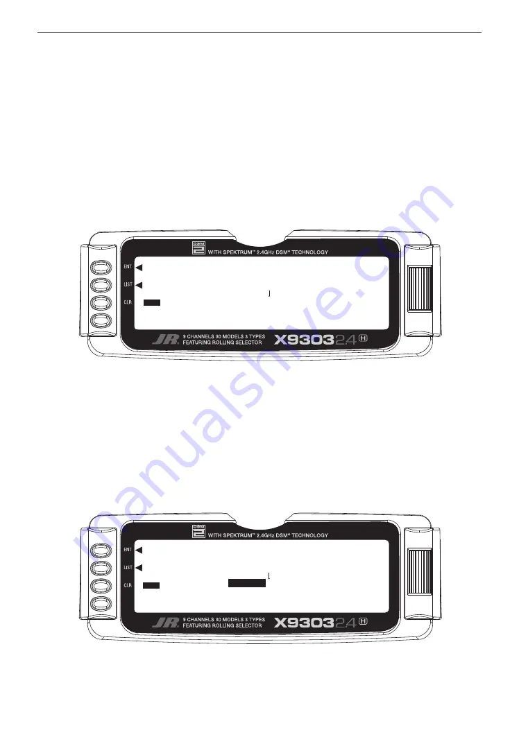
Highlight and select Select to obtain the Copy display.

The display shows the currently selected model on top 

with a down arrow pointing to the lower model memory 

that the current model will be copied into. The data that 

is presently in the lower model memory will be entirely 

replaced by the data in the currently selected model, so be 

sure that the lower model is either empty or contains data 

that is no longer required.

Copy

[Model SEL]

MODEL 3 HELI
MODEL 4 HELI

COPY

Copy

[Model SEL]

MODEL 3 HELI

MODEL 4

 HELI

COPY

Summary of Contents for X9303

Page 1: ...tivate and deactivate multiple features such as Dual Rates Gyro Gain and Governor settings using the Flight Mode switch This capability dramatically reduces the pilot s workload allowing the pilot to...

Page 2: ...deciding the model to be used any programming in this particular model will be lost 1 Bring up the SYSTEM Menu by holding down the ENT button while turning the transmitter on 1 In the SYSTEM Menu high...

Page 3: ...backup copy of the model memory protects against losing the original program and also allows one to experiment with the original program knowing that the original settings can be restored by copying...

Page 4: ...ry regard The backup copy can now be used to restore the original at any time by performing the Copy function and reversing the order of models where the backup is copied into the original Note As the...

Page 5: ...previous model or programming session If you are setting up a model for the first time you can skip this step and move to the TYPE SELECT function 1 In the SYSTEM Menu highlight and select MDL Reset...

Page 6: ...in the upper right hand corner of the main screen when the transmitter is switched on 3 Return to the SYSTEM Menu by pressing the LIST button 1 In the SYSTEM Menu highlight and select MDL Name using t...

Page 7: ...display 3 The model to be transferred must be the currently selected model If the model to be transferred is not currently selected see Model SEL in the SYSTEM Menu to select the model to be transferr...

Page 8: ...del name memory number and then scrolling to and selecting the model memory that is to receive the data Be careful to select an unused model memory or a memory that contains data for a model that is n...

Page 9: ...djusting the digital trims AILE ELEV RUDD HOVT HOVP the total trim travel does not change only the number of increments beeps changes which makes for finer or coarser trim movements When adjusting the...

Page 10: ...4 separate Flight Modes N 1 2 H There are 2 additional flight modes numbered 3 and 4 that can be activated through the Device Select function If the additional flight modes are desired please follow t...

Page 11: ...use the Selector to highlight and select THRO HOLD PIT Trim GEAR AUX2 AUX3 or AUX4 along the top line of the display 2 Once a switch is selected a list of available replacement switches is displayed H...

Page 12: ...ble to be used as a 2nd channel for a primary flight control The X9303 2 4 features a special Governor program that can be activated in the Device Select screen The Governor program is designed to be...

Page 13: ...y will reset the Swashplate Type to the factory default Normal position 5 To exit the Swashplate Type function roll the Rolling Selector to highlight LIST and press This concludes the SYSTEM Menu port...

Page 14: ...y crisp such as when performing aerobatics and then feel softer for other maneuvers such as Hovering and yet other times when we would like the helicopter to be very crisp but without the tendency to...

Page 15: ...nnel between Normal and Reverse Note If any of the versions of CCPM have been selected the 3 CCPM channels will be re named to CH2 CH3 and CH6 etc on the display The Automatic Dual Rate function allow...

Page 16: ...vos feature an odd number of splines on the output shaft you can rotate and reinstall the arms to try and obtain a better position for the servo arm that will require a lesser amount of sub trim Now u...

Page 17: ...the FUNC LIST to obtain the Travel Adjust display 2 Use the Selector to highlight and select each channel and adjust the travel in each direction by rotating the Selector The direction of travel is ch...

Page 18: ...ervos are used to move the swashplate and are spaced at 90 degrees apart This is a very common control system configuration used predominantly for Scale models like Vario Graupner etc This section is...

Page 19: ...e activated in most cases Accessing the Swashplate Mixing Function 1 Place the transmitter power switch in the ON position 2 Access the Function Mode by pressing the LIST key 3 Move the Rolling Select...

Page 20: ...o shut the engine off for autorotation a negative or zero value should be input Accessing the Throttle Hold Function 1 Place the transmitter switch in the ON position 2 Press the List key then move th...

Page 21: ...r to increase decrease the position of the cutoff point The Hold Delay function allows the throttle servos movement to be slowed when switching from Throttle Hold back to a previous Flight Mode This f...

Page 22: ...flight Note The throttle trim and hovering throttle levers are only operable when the flight mode switch is in the normal position Thus in the 1 or 2 positions these two functions have no effect Also...

Page 23: ...unction Mode 3 Roll the Rolling Selector to highlight the THRO CURV function then press to access Note The letter numbers directly to the right of THRO CURV at the top left of the LCD displays the cur...

Page 24: ...inal settings of the throttle curve The throttle trim range will affect the throttle curve as shown The adjustable range of output using the hovering throttle lever is approximately 15 points as shown...

Page 25: ...tor to access Note The Letter numbers directly to the right of PIT CURV at the top right portion of the LCD is the current flight mode switch position N 1 2 3 4 or H Use NORMAL for hover curves and 1...

Page 26: ...c specifications are shown below in the form of graphs Details of the curves will differ depending on the helicopter specifications In these examples the throttle open close stroke and autorotation pi...

Page 27: ...nction then press the Rolling Selector to access 4 Move the Rolling Selector to highlight the desired Revo Mix value to be adjusted Press the Rolling Selector to open the desired value Rotate the Roll...

Page 28: ...ter switch in the ON position 2 Press the LIST key to enter the Function mode 3 Move the Rolling Selector and highlight the GYRO SENS function Press the Rolling Selector to access 4 Highlight INH with...

Page 29: ...g from load changes placed upon the engine when an Aileron Elevator or Rudder control is given Mixing Cyclic to Throttle Mixing The most common use for Cyclic to Throttle mixing is for Stunt Modes 1 4...

Page 30: ...throttle value to this mix when rudder is applied the throttle is advanced or reduced depending on the desired change in rpm A good starting value would be 15 for R right mixing and 10 for L left mix...

Page 31: ...djusted with the Rolling Selector and then press to open the options box Roll the Rolling Selector to adjust the value as needed The X9303 2 4 allows you to select the specific Flight modes when the C...

Page 32: ...ce the transmitter switch in the ON position 2 Press the LIST key to enter the Function mode 3 Move the Selector and highlight the GOVERNOR function Press the Selector to access 4 Highlight the desire...

Page 33: ...mixing bypasses any other mixing that might affect that channel such as throttle curves or other programming and uses the stick position only to control the mix There are also 4 options for Master ch...

Page 34: ...as the Master and the Ailerons as the Slave For this type of Mix you would use Standard Program Mixes 3 through 6 Activating Retractable Gear via the Flight Mode switch This form of mix would allow yo...

Page 35: ...highlight and select INH to obtain the main mix display The example is using PROG MIX3 1 Select Master All Programmable Mixers default to Throttle as both the Master and the Slave THRO THRO The first...

Page 36: ...r to Aileron mixing value is also required for Down Elevator move the Elevator stick to the down position The upper POS 1 value will then be highlighted and can be adjusted as needed 5 Offset Leave th...

Page 37: ...on of Aileron Setup Tip Most helicopters that have a Clockwise Rotation Rotor require a small amout of Up Elevator for right rolls and a small amount of Down Elevator for left rolls Highlight and sele...

Page 38: ...to a low negative or positive value check elevator function for proper direction you want up elevator to a starting value of between 3 and 5 This is the amount of deflection of the Elevator Slave chan...

Page 39: ...ix can be turned on and off via the Flight Mode switch so that you can activate the mix only in the flight modes where the trim change is noted The Mix parameters will be selected and set in the follo...

Page 40: ...s to access the values Move the throttle stick to the full high position and the upper value next to Pos0 should be highlighted Set the higher Pos0 parameter to a low negative or positive value check...

Page 41: ...btain the first Multi Point Programmable Mix display Then press ACT next to CLR or highlight and select INH to obtain the main mix display The example is using PROG MIX1 Flight Mode switch in Normal p...

Page 42: ...s NRM ST1 ST2 and HLD Flight Mode Switch in ST1 Position Flight Mode Switch in ST2 Position Flight Mode Switch in Hold Position PROG Mix1 Point 0 Point 1 Point 2 Point 3 Point 4 Point 5 Point 6 0 80 8...

Page 43: ...Mode Gear Down Point 2 80 Stunt 1 Gear Up Point 3 80 Stunt 2 Gear Up Point 4 INH Stunt 3 if Activated Point 5 INH Stunt 4 if Activated Point 6 80 Throttle Hold Gear Down 7 EXP Expo With this mixing ex...

Page 44: ...he FUNCTION LIST to obtain the Trainer Display 4 If the X9303 2 4 is being used as the Master transmitter the transmitter operated by the instructor select the channel s that are to be operated by the...

Page 45: ...witch to SLAVE A message will appear instructing to Connect DSC POWER off Make sure the transmitter power switch is in the OFF position and the DSC cord is connected between the 2 transmitters The X93...

Page 46: ...1 To configure the timer as a Countdown timer highlight and select Timer in the FUNCTION LIST to obtain the Timer display Highlight and select INH under TIMER and then select DOWN T Use the Selector...

Page 47: ...on highlight and select MONITOR in the FUNCTION LIST to obtain the Monitor display 2 The default display MONI shows the settings of all digital trims To view the Monitor display of all channels highli...

Page 48: ...L R U D PROGRAMMABLE MIX MIX1 MIX1 MIX1 MIX1 MIX1 MIX1 CHANNEL SW EXP 0 1 2 3 4 5 6 ON OFF EXP 0 1 2 3 4 5 6 ON OFF POS POS OFFSET ON OFF POS0 POS1 POS2 AUTO D R ACT INH ACT INH ACT INH AUX2 AUX3 GEAR...

Reviews: