


With the system hooked up as shown, insert the bind plug in the charge plug
1.
receptacle. The switch must be a 3-wire type switch (JRPA001 or JRPA004) to enter
the bind mode through the switch. If a 3-wire switch is not available, install the male
bind plug into the charge plug receptacle and power the receiver through any other
open port to enter bind mode.
Turn on the receiver switch. Note that the LEDs on both receivers should be flashing,
2.
indicating that the receiver is ready to bind. To program SmartSafe™, leave the bind
plug in the receiver during the entire bind process. To program Preset Fail-safe with
the LEDs flashing, remove the bind plug prior to step 4. This will program the
receiver in the Preset Fail-safe mode.
Establish the desired fail-safe stick positions: normally low throttle and flight
3.
controls neutral.
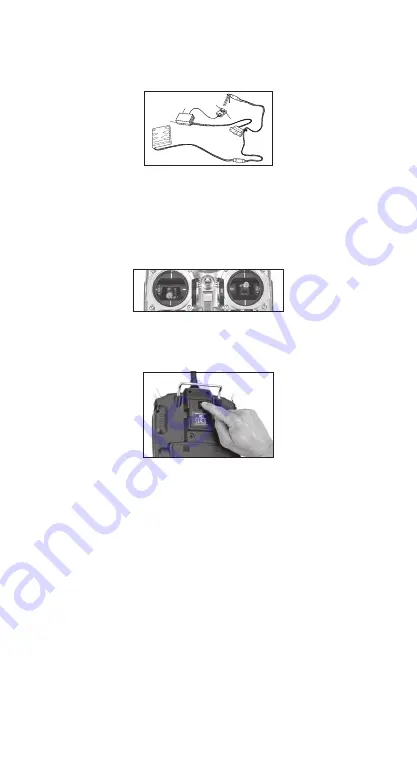
Press and hold the bind button on the back of the transmitter while turning on the
4.
power switch. The bind button should flash and within a few seconds the system
should connect. The LEDs on the receivers should go solid, indicating the system
has connected.
Remove the bind plug and store it in a convenient place.
5.
After you’ve programmed your model, it’s important to rebind the system
6.
so the true low throttle and neutral control surface positions are programmed.
Note
: To bind an aircraft with an electronic speed controller that powers the
receiver through the throttle channel (BEC), insert the bind plug into the
battery port and proceed to Step #2.
The R921X features two types of fail-safe:
SmartSafe
™
Fail-safe
SmartSafe is ideal for most types of electric aircraft and is also recommended for most types
of gas- and glow-powered models. With SmartSafe, when signal is lost the throttle channel
only is driven to its preset fail-safe position (normally low throttle) while all other channels
hold last command. Here’s how SmartSafe works:
Receiver power only
When the receiver only is turned on (no transmitter signal is present), all servos except for
throttle are driven to their preset fail-safe positions, normally control surfaces at neutral and
the landing gear down. These fail-safe positions are stored in the receiver during binding. At
this time the throttle channel has no output, to avoid operating or arming the electronic speed
control. In glow-powered models, the throttle servo has no input signal so it remains in its
current position.


