Johnson J2R4SUC 2007 Service Manual Download Page 41

MAINTENANCE

INSPECTION AND MAINTENANCE SCHEDULE

39

3

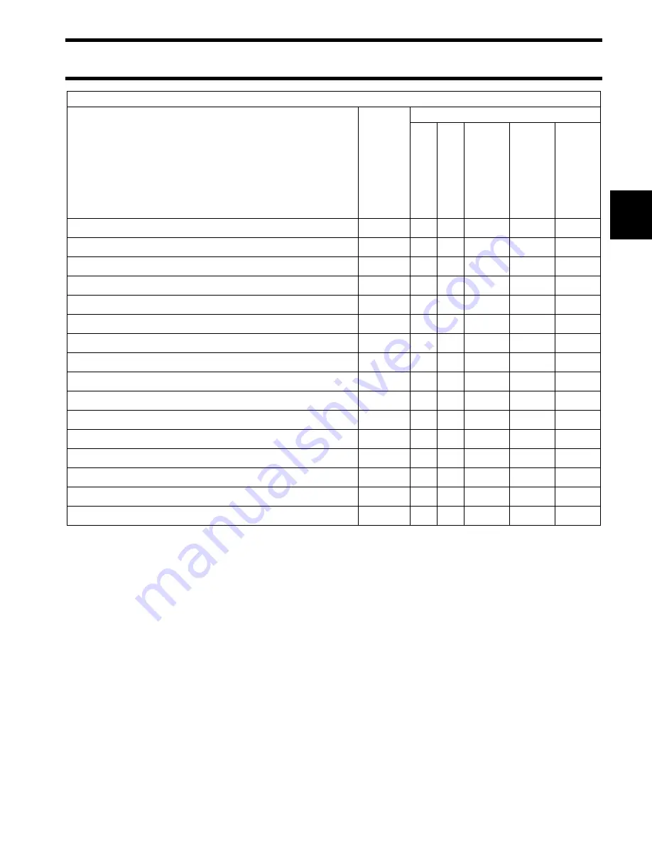
Crankcase oil, replace 

(2)

H

3

3

Oil filter, replace

3

3

Valve tappet clearance, inspect 

(3)

3

3

Engine upper and lower motor covers, clean and wax

3

Starter pinion shaft, inspect and lubricate

F

3

Gearcase lubricant, inspect fill level and condition of lube

B

3

Propeller shaft, inspect and lubricate

D

3

Spark plugs, replace 

(3)

3

Decarbonize

G

3

Operator’s Guide, review

3

Breather and fuel line, replace

3

Carburetor, inspect

3

Driveshaft splines, inspect and lubricate

E

3

Fuel filter, replace

3

Ignition timing, inspect

3

Water pump, inspect and replace

3

(1) Also recommended at 10-Hour Inspection

(2) Replace every 100 hours or annually if 

Ultra 4-Stroke

 oil is not used.

(3) Emission-related component

A

Evinrude/Johnson

 Anti-Corrosion Spray or 

Evinrude/Johnson

 “6 in 1” Multi-Purpose Lubricant

B

HPF XR

 Gearcase Lubricant

C

Power Trim/Tilt and Power Steering Fluid

D

Triple-Guard

 Grease

E

Evinrude/Johnson Moly Lube

F

Starter Bendix Lube Only

G

Evinrude/Johnson

 Engine Tuner

H

Evinrude/Johnson Ultra 4-Stroke

 synthetic blend oil

Engine Maintenance and Inspection Schedule

Description

Engine 

Care 

Product

Frequency

Each Use

10-Hour 

Inspection

Every 50 Hours 

or 6 

mon

ths

Every 100 Hours 

or An

nually

Every 200 Hours 

or Bian

nually

Summary of Contents for J2R4SUC 2007

Page 1: ......

Page 2: ......

Page 3: ...ubriplate is a registered trademark of Fiske Brothers Refining Company NGK is a registered trademark of NGK Spark Plugs U S A Inc NMEA is a registered trademark of the National Marine Electronics Asso...

Page 4: ...l and never rush or guess a service pro cedure Human error is caused by many factors carelessness fatigue overload preoccupation unfamiliarity with the product and drugs and alco hol use to name a few...

Page 5: ...ard may drop unexpectedly Avoid personal injury always support the outboard s weight with a suitable hoist or the tilt support bracket during service To prevent accidental starting while servicing twi...

Page 6: ...ICE SPECIFICATIONS AND SPECIAL TOOLS 15 2 INSTALLATION AND PREDELIVERY 27 3 MAINTENANCE 37 4 IGNITION AND ELECTRICAL 53 5 FUEL SYSTEM 61 6 POWERHEAD 73 7 MIDSECTION 107 8 GEARCASE 119 9 MANUAL STARTER...

Page 7: ...G MODEL AND SERIAL NUMBERS 6 MODEL DESIGNATION 7 TYPICAL PAGE A 8 TYPICAL PAGE B 9 TYPICAL PAGE C 10 TYPICAL PAGE D 11 ABBREVIATIONS USED IN THIS MANUAL 12 UNITS OF MEASUREMENT 12 LIST OF ABBREVIATION...

Page 8: ...talog for part numbers and for exploded views of the outboard which are a valuable aid to disassembly and reas sembly Identifying Model and Serial Numbers Outboard model and serial numbers are located...

Page 9: ...SUFFIX DESIGN FEATURES AP Advanced Propulsion B Blue Paint C Counter Rotation D Evinrude E TEC E Electric Start w Remote Steering F Direct Injection G Graphite Paint H High Output J Jet Drive M Milita...

Page 10: ...e units appear as in lbs Use appropriate torque Tightening torque for a fastener Subsection title indicates beginning of the subsection Italic subheading above Service Chart indicates pertaining model...

Page 11: ...CAL PAGE B 9 TYPICAL PAGE B Section Title Section Title Section Title Subsection Title Model specific illustrations designated with image captions Products and lubricants italicized Products and lubri...

Page 12: ...ning a particular model Title indicates from this point All Models are concerned Denotes necessary step or information to prevent damage or control correct procedure Title indicates the procedure spec...

Page 13: ...for lower pulse hose of V4 or V6 Models Cross references direct readers to related topics Cross references direct readers to related topics Illustration components numbered to correspond to image Sec...

Page 14: ...dead center AT air temperature sensor BPS barometric pressure sensor BTDC before top dead center CCA cold cranking amps CPS crankshaft position sensor DI Direct Injection ECU electronic control unit...

Page 15: ...may not depict actual models or equipment but are intended as representative views for refer ence only Certain features or systems discussed in this manual might not be found on all models in all mar...

Page 16: ...rement for resis tance Values When precedes a value on the meter face the reading should be less than or equal to the value shown When precedes a value on the meter face the reading should be greater...

Page 17: ...ECIAL TOOLS TABLE OF CONTENTS TECHNICAL DATA 16 STANDARD TORQUE SPECIFICATIONS 18 TIGHTENING TORQUE IMPORTANT FASTENERS 18 TIGHTENING TORQUE GENERAL BOLT 19 SPECIAL TOOLS 20 ELECTRICAL IGNITION 20 FUE...

Page 18: ...m Compression ratio 9 0 1 FUEL SYSTEM Carburetion One single throat carburetor float feed Main Jet 70 Pilot Jet 32 Starting Enrichment Manual Float Level Setting 10 2 mm Preferred Fuel Regular unleade...

Page 19: ...hermostat opens 118 to 126 F 48 to 52 C IGNITION Type Transistorized RPM Limit 6500 RPM Spark Plugs NGK CR6HSA 0 030 in 0 76 mm Gap 0 024 to 0 028 in 0 6 to 0 7 mm Ignition Timing 30 BTDC GEARCASE Gea...

Page 20: ...rod cap bolt 5 mm 7 0 7 5 0 Valve adjusting lock nut 5 mm 7 0 7 5 0 Intake pipe bolt 6 mm 11 1 1 8 0 Carburetor mounting bolt 6 mm 10 1 0 7 0 Flywheel nut 10 mm 45 4 5 32 5 Igniter unit bolt 6 mm 10...

Page 21: ...ked bolt 10 mm 22 35 2 2 3 5 16 0 25 5 5 mm 2 4 0 2 0 4 1 5 3 0 6 mm 6 10 0 6 1 0 4 5 7 0 8 mm 15 20 1 5 2 0 11 0 14 5 Stainless steel bolt 10 mm 34 41 3 4 4 1 24 5 29 5 5 mm 3 6 0 3 0 6 2 0 4 5 6 mm...

Page 22: ...ical Ignition Digital multimeter Ohms resolution 0 01 Purchase through local supplier DRC7265 Ignition analyzer P N 501890 49791 CD Peak reading voltmeter P N 507972 49799 Spark checker P N 508118 497...

Page 23: ...case filler P N 501882 49790 Gearcase pressure tester P N 507977 Stevens P N S 34 Gearcase vacuum tester P N 507982 Stevens P N V 34 49794 Dial indicator set Universal pinion bearing remover and insta...

Page 24: ...037485 005515 Crankshaft upper seal remover installer kit P N 391060 9 9 15 HP 23102 Cylinder bore gauge P N 771310 45303 Tappet adjusting tool P N 341444 38202 Valve lifter adapter kit P N 5000899 00...

Page 25: ...acement jaws P N 437952 23150 Puller jaws large P N 432129 replacement jaws P N 437954 23148 Puller jaws bearing P N 432130 replacement jaws P N 437953 23149 Slide hammer P N 391008 CO1577 Slide hamme...

Page 26: ...ant P N 777192 Ultra 4 Stroke Outboard Oil P N 775594 HI VIS Gearcase Lube P N 775605 Engine Tuner P N 777185 D P L Spray P N 777183 4 Stroke Outboard Oil P N 775597 Triple Guard Grease P N 508298 Ant...

Page 27: ...briplate 777 P N 317619 2 4 Fuel conditioner P N 775613 Needle Bearing Grease P N 378642 Power Trim Tilt and Power Steering Fluid P N 775612 Black Neoprene Dip P N 909570 Fuel System Cleaner P N 77718...

Page 28: ...P N 772666 ThreeBond 1104 P N 351052 ThreeBond 1207B P N 351053 Pipe Sealant with Teflon P N 910048 Locquic Primer P N 772032 Permatex No 2 P N 910032 Thermal Joint Compound P N 322170 1 Screw Lock P...

Page 29: ...NG AND DRILLING 29 HULL CENTERLINE 29 TRANSOM HEIGHTS 29 TRANSOM DRILLING LOCATIONS 29 LIFTING THE OUTBOARD 30 OUTBOARD MOUNTING 30 FUEL AND OIL 31 FUEL REQUIREMENTS 31 OIL REQUIREMENTS 32 RUNNING CHE...

Page 30: ...lash well area pro vide adequate clearances The top edge of the transom should be wide enough to allow full steering travel The ABYC standard for most single outboard installations is 33 in 84 cm Chec...

Page 31: ...the port and starboard chines Transom Heights Make sure the transom height is consistent with the height of the outboard to be installed A 19 to 21 in 48 3 to 53 3 cm transom height uses a 20 in 50 8...

Page 32: ...cket OUTBOARD MOUNTING Fastening the Outboard to the Transom IMPORTANT Follow all directions carefully The outboard s warranty will not cover product damage or failure resulting from incorrect out boa...

Page 33: ...content does not exceed 10 ethanol by volume 5 methanol with 5 cosolvents by volume WARNING If either side of the transom deforms or cracks when the bolts are tightened to their recommended torque the...

Page 34: ...s and will remove moisture from the fuel system It can be used con tinuously and should be used during any period when the outboard is not being operated on a reg ular basis Its use will reduce spark...

Page 35: ...r 1 2 throttle only With easy planing boats use full throttle to quickly accelerate boat onto plane Immediately reduce throttle to one half as soon as the boat is on plane BE SURE boat remains on plan...

Page 36: ...r Prevention Start outboard and shift outboard into FORWARD Turn outboard OFF while lever is in FORWARD Attempt to restart the outboard Outboard should not start Water Pump Overboard Indicator A stead...

Page 37: ...the boat has a normal load in it Refer to TECHNICAL DATA on p 16 To compensate for changes in boat loading the engine s full throttle RPM must be verified peri odically IMPORTANT If the propeller bla...

Page 38: ...then bend its ends to secure the propeller IMPORTANT After fastening cotter pin make sure outboard is in NEUTRAL and carefully spin propeller Propeller must turn freely and should not spin off center...

Page 39: ...TAKE SCREEN 42 WATER PUMP 42 FUEL SYSTEM 43 BREATHER AND FUEL LINE 43 FUEL FILTER 43 CARBURETOR 43 LUBRICATION 43 ENGINE OIL 43 GEARCASE LUBRICANT 44 LINKAGES AND FITTINGS 45 SPARK PLUG 46 VALVE CLEAR...

Page 40: ...ct and lubricate 1 D Every 60 days Every 30 in Saltwater Throttle linkage inspect and lubricate 1 D Every 60 days Every 30 in Saltwater Steering bracket lubricate 1 D Every 60 days Every 30 in Saltwat...

Page 41: ...ce 3 Ignition timing inspect 3 Water pump inspect and replace 3 1 Also recommended at 10 Hour Inspection 2 Replace every 100 hours or annually if Ultra 4 Stroke oil is not used 3 Emission related comp...

Page 42: ...mination Fasteners tighten loose components Thermostat operation Engine to transom mounting hardware Electrical and ignition wires and connections ANTI CORROSION PROTECTION Sacrificial Anodes Galvanic...

Page 43: ...following Remove the anode and clean the area where the anode is installed Clean the mounting screws Install the anode and test again Metallic Component Protection Protect metal components on outboar...

Page 44: ...ard s clamp screws for thickness Be sure water covers the water intakes START outboard Run outboard at IDLE only for at least five minutes IMPORTANT To prevent damage do not run outboard above fast id...

Page 45: ...Refer to INSPECTION AND MAINTENANCE SCHEDULE on p 38 for oil change schedule IMPORTANT Engine oil should be changed while engine is warm Place outboard upright on a level surface Remove the oil filler...

Page 46: ...icant IMPORTANT Always check the fill level of the gearcase lubricant prior to removing drain fill plug A tie strap can be used to check lubricant level Examine drained lubricant for excessive metal f...

Page 47: ...Guard grease to the points shown WARNING When servicing the propeller always shift the outboard to NEUTRAL position and twist and remove all spark plug leads so the engine cannot be started accidenta...

Page 48: ...plug Remove four screws and cylinder head cover Rotate the flywheel clockwise to bring the piston to Top Dead Center TDC on compression stroke IMPORTANT Rotate the crankshaft in the nor mal running d...

Page 49: ...tion adjust valve clearance IMPORTANT The valve clearance specification is for COLD engine condition Adjustment Loosen the valve adjusting lock nut while holding the valve adjusting screw Turn valve a...

Page 50: ...before the engine cover can be completely removed Tie a knot in the rope inside the engine cover in order to prevent the rope from winding onto the recoil reel when the starter grip is removed Untie t...

Page 51: ...e throttle stop screw Clockwise Engine speed increases Counterclockwise Engine speed decreases IGNITION TIMING IMPORTANT Before checking ignition timing make sure idle speed is adjusted within specifi...

Page 52: ...plug hole Turn the flywheel in a clockwise direction to dis tribute the fogging oil throughout the cylinder Install and torque the spark plug IMPORTANT DO NOT restart outboard until it goes back into...

Page 53: ...ere Engine Dropped Overboard Not Running Disconnect battery cables at the battery Rinse powerhead with clean water Remove spark plug leads and spark plugs Place outboard in horizontal position cylinde...

Page 54: ...s rotated it may indicate a bent connecting rod and no attempt should be made to start the outboard Powerhead must be disassembled and serviced immediately Engine Dropped Overboard In Salt Water Follo...

Page 55: ...NITION AND ELECTRICAL TABLE OF CONTENTS SERVICE CHART 54 OPERATION 55 TROUBLESHOOTING 57 IGNITION TESTS 58 IGNITER UNIT 58 SPARK PLUG CAP 58 ENGINE STOP SWITCH 58 COMPONENT SERVICING 59 IGNITER AIR GA...

Page 56: ...nd C Adhesive 847 D Moly Lube F Blue Nut Lock R DPL Penetrating Lube W HPF XR Gear Oil 1 Flywheel 2 Ignition coil 3 Bolt 4 Nut 5 Key 6 Cap spark plug 7 Seal spark plug 8 Seal high tension cord 9 Switc...

Page 57: ...4 OPERATION The outboard uses a transistorized ignition circuit The ignition system consists of a flywheel magneto an igniter unit a spark plug and an emergency stop switch Igniter unit Spark plug Em...

Page 58: ...R2 and R3 connected in parallel to the primary circuit As the flywheel turns further the terminal voltage of the resistor R3 in the resistor circuit R2 and R3 rises to the level of work ing voltage o...

Page 59: ...er to Igniter Unit on page 58 Primary 0 5 to 0 9 k Secondary 10 to 16 k Check the spark plug cap for any evidence of a high tension leak Check the spark plug cap resistance Refer to Spark Plug Cap on...

Page 60: ...k Plug Cap Resistance Test Measure spark plug cap resistance Spark plug cap resistance 8 to 12 k If measurement is out of specification replace the spark plug cap Engine Stop Switch Check continuity o...

Page 61: ...unit and remove the two bolts securing the igniter unit Use strap type flywheel holder P N 507976 or equivalent to loosen the flywheel nut IMPORTANT Do not remove the flywheel nut It prevents damage t...

Page 62: ...Igniter Unit Install the igniter unit with an air gap of 0 02 in 0 5 mm between both core ends and the fly wheel Check the gaps as shown Tighten igniter unit bolts to 7 0 ft lbs 10 N m Reconnect emer...

Page 63: ...LE OF CONTENTS SERVICE CHART 62 REMOVAL 64 CARBURETOR 65 DISASSEMBLY 65 CLEANING AND INSPECTION 66 REASSEMBLY 67 INSTALLATION 68 LEAKAGE CHECK 69 THROTTLE ADJUSTMENT 69 FUEL TANK 70 REMOVAL 70 INSPECT...

Page 64: ...5 Float 6 Pin float 7 Spring 8 Gasket 9 Chamber float 10 Gasket 11 Screw 12 Spring 13 Screw 14 Screw 15 Jet pilot 30 Jet pilot 32 Jet pilot 34 16 Screw 17 Jet air 170 18 Jet pilot air 145 19 Gasket 2...

Page 65: ...63 5 1 Tank fuel 2 Bracket fuel tank 3 Cap assembly fuel tank 4 Gasket tank cap 5 Cushion 6 Grommet fuel tank 7 Rubber fuel tank grommet 8 Valve assembly fuel 9 Clip fuel hose 10 Hose fuel valve to c...

Page 66: ...and air silencer Remove fuel hose from the carburetor Inspect the fuel hose If cracks swelling or other damage is found replace the fuel hose WARNING Gasoline is extremely flammable and highly explosi...

Page 67: ...lot jet Remove the bolt and the float chamber Remove the float pin the float and the float spring IMPORTANT Always remove the float pin from the right side to the left side 1 Idle adjusting screw 2 Sc...

Page 68: ...r deterioration will result Do not use a wire or a small drill bit in order to clean the orifices and jets of the carburetor Carburetor Body and Float Chamber Inspect the carburetor body and the float...

Page 69: ...reverse order of disassembly with special attention to the following steps Install the main nozzle to the carburetor body before installing the main jet Install the float with needle valve Install th...

Page 70: ...the pilot jet pilot air jet and main air jet INSTALLATION Installation is reverse order of removal with spe cial attention to the following steps IMPORTANT Do not re use the removed gas ket Always us...

Page 71: ...ully close the throttle control grip Turn the idle adjusting screw counterclockwise until the screw does not touch the stopper plate Insert the throttle control inner cable into the link age hole Whil...

Page 72: ...he connecting screw and remove the fuel cock from the fuel tank Inspection Check the filter If clogged or damaged is found clean the filter or replace the fuel cock Inspect the fuel cock If leakage de...

Page 73: ...k replace the tank cap Installation Installation is reverse order of removal with spe cial attention to the following steps Place the fuel tank bracket in position Install the fuel tank and recoil sta...

Page 74: ...72 FUEL SYSTEM NOTES NOTES Technician s Notes Related Documents Bulletins Instruction Sheets Other...

Page 75: ...MBLY 78 CLEANING AND INSPECTION 80 ASSEMBLY 84 INSTALLATION 86 CYLINDER CRANKCASE PISTON 87 DISASSEMBLY 87 INSPECTION 89 ASSEMBLY 96 THERMOSTAT 101 REMOVAL 101 INSPECTION 101 INSTALLATION 102 INSTALLA...

Page 76: ...0 17 0 005 0 007 Valve clearance Cold engine condition EX STD mm in 0 13 0 17 0 005 0 007 Valve seat angle IN 45 Valve seat angle EX 45 Valve guide to valve stem clearance IN STD mm in 0 010 0 037 0...

Page 77: ...n clearance in piston pin hole STD mm in 0 002 0 013 0 0001 0 0005 Limit mm in 0 040 0 0016 Piston pin outside diameter STD mm in 11 995 12 000 0 4722 0 4724 Limit mm in 11 980 0 4717 Piston pin hole...

Page 78: ...ues shown are guidelines only not absolute service limits If engine shows a variation in test check for Excessively worn cylinder wall Worn piston Worn or stuck piston ring Poor seating of valves Rupt...

Page 79: ...e carburetor assembly Refer to CARBURETOR on p 65 Remove the igniter unit and flywheel magneto Refer to Removal on p 59 Remove the tiller handle assembly Refer to Tiller Handle on p 112 Remove the fou...

Page 80: ...ts then the valve adjusting screw Remove the rocker arm shaft and the rocker arms Remove the push rods Remove the cylinder head gasket and the five cyl inder head bolts from the cylinder block 1 Bolt...

Page 81: ...haft Remove the valve springs IMPORTANT Reassemble each valve spring to its original position Remove the intake valve and exhaust valve Remove the valve stem seals IMPORTANT Do not re use the removed...

Page 82: ...intake and the exhaust ports the combustion chamber and the head surface Valve Seat Inspect the valve seats for cracks or other dam age Cylinder Head Distortion Using a straightedge and thickness gaug...

Page 83: ...acks or other damage Replace if necessary Measure the rocker arm shaft hole diameter using a small bore gauge Rocker arm shaft hole diameter 0 1581 to 0 1585 in 4 015 to 4 027 mm Measure the rocker ar...

Page 84: ...037 mm EX 0 0010 to 0 0020 in 0 025 to 0 052 mm Service limit IN 0 0030 in 0 075 mm EX 0 0035 in 0 090 mm If the measurement exceeds the service limit replace the valve and or the cylinder head If una...

Page 85: ...hickness Measure the thickness of the valve head Valve head thickness IN EX 0 02 in 0 5 mm If the measurement exceeds the service limit replace the valve Valve Seat Contact Width Measure the valve sea...

Page 86: ...ength Standard IN EX 0 883 in 22 42 mm Service limit IN EX 0 847 in 21 52 mm If the measurement exceeds the service limit replace the valve spring Valve Spring Preload Measure the valve spring preload...

Page 87: ...th thumbs so the valve stem can be inserted into the side hole of the retainer and let it slide sidewise into the cen ter hole Make sure the retainers are properly seated in groove IMPORTANT Do not re...

Page 88: ...inal torque 9 5 ft lbs 13 N m Install the push rods onto the cam rocker arms Install the rocker arms and the rocker arm shaft Adjust the valve clearance Refer to VALVE CLEARANCE on p 46 Install the cy...

Page 89: ...e under oil seal plate Remove the eight bolts and the crankcase Remove the thrust washer Remove the cam rocker arm washer cam rocker arm spring washer and shaft Remove the oil pump shaft camshaft and...

Page 90: ...ylinder block Remove the circlips the piston pin the connecting rod and the piston rings from the piston Remove the screw and the oil pump outer plate Remove the inner rotor and the outer rotor 1 Bolt...

Page 91: ...defec tive or other damage is found on any component replace Camshaft Inspect the camshaft face for scratches and wear Measure the camshaft height Cam height Standard IN EX 1 1213 to 1 1291 in 28 480...

Page 92: ...rement exceeds the service limit resurface or replace the cylinder IMPORTANT The cylinder can be resurfaced using a surface plate and a 400 grit wet sandpa per Move the cylinder in a figure eight patt...

Page 93: ...surface at a right angle to the crankshaft pin Piston skirt diameter at 5 mm elevation from the skirt end Piston to cylinder clearance Standard 0 0007 to 0 0013 in 0 018 to 0 033 mm Service limit 0 00...

Page 94: ...dard Oil 0 059 to 0 060 in 1 51 to 1 53 mm Piston ring thickness Standard First and Second Ring 0 046 to 0 047 in 1 17 to 1 19 mm Measure the piston ring end gap with the piston ring in the lowest pos...

Page 95: ...1 980 mm Piston pin hole diameter Standard 0 4725 to 0 4728 in 12 002 to 12 008 mm Service limit 0 4736 in 12 030 mm Connecting rod small end inside diameter Standard 0 4727 to 0 4730 in 12 006 to 12...

Page 96: ...rque 2 5 ft lbs 5 N m Final torque 5 0 ft lbs 7 N m IMPORTANT Do not rotate the connecting rod with the plastigauge in place Remove the connecting rod and the connecting rod cap from the crank pin Mea...

Page 97: ...re use the oil seal once removed Always use a new oil seal Drive the oil seal down into position as shown Oil Pump Inspect the outer rotor the inner rotor and the rotor plate for excessive wear or oth...

Page 98: ...cting Rod Apply engine oil to the piston pin the piston pin bore and the connecting rod Fit the connecting rod to the piston as shown and insert the piston pin through the piston and the connecting ro...

Page 99: ...iston rings so the ring gaps are stag gered at approximately 90 degree angles IMPORTANT Failure to stagger the piston ring gaps may result in the crankcase oil dilution Crankshaft and Piston to Cylind...

Page 100: ...the connecting rod cap Install the connecting rod cap in the direction shown Apply engine oil lightly to the connecting rod bolts Tighten the two connecting rod bolts in two steps First torque 2 5 ft...

Page 101: ...arm IMPORTANT Be sure the cam rocker arms are positioned as shown Oil Pump Apply engine oil to the inner rotor and the outer rotor Install the inner rotor and the outer rotor in the crankcase as shown...

Page 102: ...on crankshaft Apply engine oil to the crank journals Apply engine oil to the crankcase bearing the crankshaft lower oil seal and the driveshaft oil seal Install crankcase on the cylinder block Tighten...

Page 103: ...ll the thermostat Refer to THERMOSTAT on p 101 THERMOSTAT Removal Remove the recoil starter assembly Refer to MANUAL STARTER on p 139 Remove the four bolts and thermostat cover Remove the thermostat I...

Page 104: ...eleases the thread Thermostat operating temperature 118 to 126 F 48 to 52 C Installation Installation is reverse order of removal with spe cial attention to the following steps Install the thermostat...

Page 105: ...o the seal lips of drive shaft oil seal Install the oil seal protector and tighten the bolt after applying Nut Lock to the bolt Secure the powerhead to the lower cover and tighten the four bolts to th...

Page 106: ...s in order to ensure proper and safe operation of the outboard All parts removed have been returned to the original positions Midsection gear engagement is properly adjusted Refer to GEAR SHIMMING AND...

Page 107: ...d the thermostat in the cylinder This system cools both the power head and the exhaust If overheating occurs the components of the cooling system must be inspected for blockage corrosion build up or d...

Page 108: ...SYSTEM A camshaft driven trochoid type pump provides lubrication to all required powerhead components Crankshaft upper bearing Connecting rod Piston Timing gear Lower bearing ENGINE OIL Lower crankcas...

Page 109: ...7 MIDSECTION TABLE OF CONTENTS SERVICE CHART 108 REMOVAL 110 CLAMP BRACKET 111 SWIVEL BRACKET 111 TILLER HANDLE 112 INSPECTION 114 ASSEMBLY 115 SWIVEL BRACKET 115 CLAMP BRACKET 116 LUBRICATION 117 TIL...

Page 110: ...ip throttle 3 Spacer tiller handle 4 Bushing tiller handle 5 Mount tiller handle 6 Washer tiller handle 7 Bolt handle pivot 8 Knob throttle adjust 9 Nut throttle adjust knob 10 Case throttle upper 11...

Page 111: ...et swivel port 2 Bracket swivel starboard 3 Bushing steering upper 4 Bolt swivel bracket 5 Bolt swivel shaft 6 Nut swivel shaft 7 Washer swivel shaft 8 Washer tilt friction 9 Block thrust 10 Mount low...

Page 112: ...k wing nut Remove the tilt lock spacer Remove the swivel shaft nut and swivel shaft washer Remove the port side clamp bracket and tilt fric tion washer Remove the tilt lock bolt and the thrust block w...

Page 113: ...swivel bracket Take out the steering adjuster plate with the steer ing adjuster rubber Remove the stopper bracket Swivel Bracket Remove the starboard side swivel bracket 1 Side clamp bracket starboard...

Page 114: ...lead of the emergency engine stop switch Remove the plus lead of the emergency engine stop switch from the igniter unit Remove the throttle cable clamps Remove the handle pivot bolt and tiller handle...

Page 115: ...ove the two throttle cable screws Take out the throttle lower case and the throttle upper case from the tiller handle Remove throttle cable end from the tiller handle Remove the throttle grip from the...

Page 116: ...or other damage is found replace Clamp Bracket Swivel Bracket Inspect the clamp brackets and swivel bracket Steering Upper Bushing Inspect the upper bushings Stopper Bracket Stopper Spring Inspect th...

Page 117: ...Bracket After completing reassembly of the midsection apply Triple Guard grease through grease nipple Apply Triple Guard grease to the following parts Inside and outside surfaces of the bushings Insid...

Page 118: ...tilt friction washer and the swivel shaft bolt Install the thrust block with the lower thrust mount and the tilt lock bolt Install the tilt friction washer and the clamp bracket port side Install the...

Page 119: ...following steps Apply Triple Guard grease to the throttle handle mount Install the throttle handle mount in position Install the throttle handle spacer and the throttle handle bushings Install the ti...

Page 120: ...othly from the fully closed position to the fully opened position Install the choke rod connector to the carburetor Install the choke rod to the choke rod connector Check that the choke control operat...

Page 121: ...22 DRAINING 122 INSPECTION 122 FILLING 123 LEAK TEST 123 REMOVAL 124 PROPELLER SHAFT 126 WATER PUMP 127 INSPECTION 127 ASSEMBLY 131 LUBRICATION 131 PROPELLER SHAFT 132 WATER PUMP 133 SHIFT ROD 134 INS...

Page 122: ...sher 10X14X1 6 Washer 10X14X1 7 Washer 10X16X1 8 Washer 10X16X1 9 Washer 10X16X2 0 EPC4237 EPC4238 1 Case gear white 2 Bolt 6X35 3 Anode protection 4 Bolt anode protection 5 Gasket drain plug 6 Plug d...

Page 123: ...nd D Moly Lube F Blue Nut Lock R DPL Penetrating Lube 1 Case water pump 2 Seal water pump case 3 Sleeve water pump case 4 Grommet water pump case 5 Impeller water pump 6 Pin pump case impeller 7 Panel...

Page 124: ...plug and drain the lube from the gear case into a container Inspect the lubricant for metal chips The presence of metal fuzz can indicate normal wear of the gears bearings or shafts within the gearcas...

Page 125: ...he gearcase with HPF XR gearcase lube through the drain fill hole until it appears at the oil level hole Filling the gearcase too quickly can cause air pockets and the gearcase may not fill completely...

Page 126: ...nd drain the gear oil Remove the cotter pin then detach the propeller Remove the shear pin WARNING To prevent accidental starting while ser vicing twist and remove all spark plug leads During service...

Page 127: ...ler key and pump under panel Remove the two bolts securing the propeller shaft bearing housing Remove the propeller shaft bearing housing Remove the E ring 1 Shift rod 006209 1 Bolt 4 2 Pump case 0062...

Page 128: ...ft Separate the following parts Bearing housing Washer Propeller shaft assembly Remove the clutch dog Remove the spring and circlip 006215 1 Pinion gear 2 Pinion gear backup shim 006216 1 Forward gear...

Page 129: ...ound on the blades replace or repair the propeller Inspect the shear pin If bend or other damage is found replace the shear pin Gearcase Housing Inspect the gearcase If crack or other damage is found...

Page 130: ...d If excessive wear or other damage is found replace Inspect the clutch dog shifter If excessive wear crack chip or other damage is found replace Inspect the return spring If excessive wear or other d...

Page 131: ...seal IMPORTANT Do not re use the oil seal or the O ring once removed Always use new parts When replacing the propeller shaft bearing hous ing oil seal use a screwdriver to remove oil seals Apply Trip...

Page 132: ...he O ring If cut excessive wear or other damage is found replace IMPORTANT Do not re use the seal or O ring once removed Always use new parts Driveshaft Oil Seals Visually check the oil seals If cut n...

Page 133: ...ghtness and smoothness of operation Before final assembly be absolutely certain that all gear contact shim adjustments and toler ances are correct Failure to correctly adjust these areas will result i...

Page 134: ...gear lubricant to the bushing in the housing Install the driveshaft Install the E ring Propeller Shaft Install the circlip to the propeller shaft Insert the return spring and the clutch dog to the pro...

Page 135: ...ousing Install the propeller shaft housing assembly to the gearcase and tighten the two bolts to torque of 6 0 ft lbs 8 N m Water Pump Apply ThreeBond 1207B sealant evenly to both sides of under panel...

Page 136: ...ple Guard grease to O ring and install the O ring Install the water pump case while rotating the driveshaft clockwise in order to flex the impeller vanes in the correct direction Tighten the water pum...

Page 137: ...lubricant Refer to Filling on p 123 GEAR SHIMMING AND ADJUSTMENT If the gearcase has been rebuilt or has had com ponents replaced shimming for correct gear con tact and backlash will have to be adjus...

Page 138: ...ed Tooth Contact Pattern To check and adjust the tooth contact pattern of the pinion and forward gear apply a light coat of Prussian Blue on the convex surface of the for ward gear Install the propell...

Page 139: ...NT Do not set tooth contact in the bottom side toe contact position Chipping of the pinion gear may result Propeller Shaft Thrust Play After adjusting all gear positions measure the propeller shaft th...

Page 140: ...138 GEARCASE NOTES NOTES Technician s Notes Related Documents Bulletins Instruction Sheets Other...

Page 141: ...MANUAL STARTER 139 9 MANUAL STARTER TABLE OF CONTENTS SERVICE CHART 140 REMOVAL 141 DISASSEMBLY 142 INSPECTION 143 ASSEMBLY AND INSTALLATION 143...

Page 142: ...TARTER SERVICE CHART SERVICE CHART 1 Starter assembly recoil 2 Reel 3 Ratchet set 4 Spring spiral 5 Grip set 6 Rope 7 Pulley starter 8 Bolt 9 Bolt 10 Decal S I G P EPC4222 A A Triple Guard Grease F Bl...

Page 143: ...ve the motor cover Install the starter grip and the grip holder to the end of the rope Loosen the knot previously tied in the rope Remove the three bolts and the recoil starter assembly WARNING Avoid...

Page 144: ...spring from the recoil case Remove the recoil spring from the reel IMPORTANT Do not remove the recoil spring unless replacement is necessary Inspect the spring in the assembled position Remove the ro...

Page 145: ...mation or excessive curve is found replace ASSEMBLY AND INSTALLATION Reassembly is the reverse order of disassembly with special attention to the following steps Secure the outer end of the recoil spr...

Page 146: ...ay on the case Install the ratchet and the spring Install the friction plate Apply Screw Lock to threads of screw then tighten the screw IMPORTANT Screw is a left hand thread Rotate the reel approxima...

Page 147: ...WIRE HOSE ROUTING 145 10 WIRE HOSE ROUTING TABLE OF CONTENTS WIRING DIAGRAM 146 WIRE ROUTING 147 FUEL HOSE ROUTING 148...

Page 148: ...OSE ROUTING WIRING DIAGRAM WIRING DIAGRAM 006298 Spark plug Igniter unit Flywheel Magneto Wire color B Black EMERGENCY STOP SWITCH Emergency stop switch Lock plate IN RUN Lock plate OUT STOP Button PU...

Page 149: ...WIRE HOSE ROUTING WIRE ROUTING 147 10 WIRE ROUTING 006299 Emergency stop switch Clamp Emergency stop switch Igniter unit...

Page 150: ...o avoid contact with other parts Check that hoses do not contact rods and levers during either engine operation or standstill Extreme care should be taken not to cut abrade or cause any other damage o...

Page 151: ...AND SAFETY S 8 OUTBOARD MOUNTING SYSTEM AND SAFETY S 11 IF WEAKENED PARTS COULD FAIL LATER ON THE WATER WHEN NOT EXPECTED S 12 OUTBOARD HYDRAULIC TILT TRIM SHOCK ABSORPTION SYSTEM AND SAFETY S 13 OUTB...

Page 152: ...S 2...

Page 153: ...elf but also to protect the people around you It is impossible for this manual to cover every potentially hazardous situation you may encounter However your understanding and adherence to the recommen...

Page 154: ...ORWARD or REVERSE propeller still powered turning unknown to operator or outboard will START in gear and boat will move suddenly boat will move opposite to direction wanted by operator How can loss of...

Page 155: ...o STOP propeller What could happen If Operator cannot slow down the outboard or shift into NEUTRAL gear stop propeller Operator could panic and lose control of boat How can loss of speed control be mi...

Page 156: ...eel and ends here at the trim tab on the outboard What could happen If steering system comes apart boat might turn suddenly and circle Persons thrown into the water could be hit If steering jams opera...

Page 157: ...weaken Tilt outboard into boat then turn it transom mounted steerer stop to stop Be aware that raising or lowering outboard on transom can change a set up which was OK earlier If moved up or down even...

Page 158: ...kage must be eliminated Stray electric sparks must be avoided What could happen When not boating fuel leaking in car trunk or van or place where portable tank is stored base ment or cottage could be i...

Page 159: ...tion as shown in manual Screws Nuts Washers Tighten firmly these keep clamps in position and ends of wires from sparking Where lock washers are called for use them Spark Plug Boots Not torn or cracked...

Page 160: ...er engine cover If tank cap has an air vent valve make sure it is closed Whenever possible remove hose from outboard and from tank Store hose around ears of tank This way gasoline is trapped in tank a...

Page 161: ...s transom Outboard may S L I D E on transom Boat may turn and be hard to steer Outboard may T I L T on transom Boat may turn and be hard to steer If outboard hits something solid and does not stay on...

Page 162: ...d may come loose Mount on flat surface only Use shims to make surface flat Use bolts nuts and washers supplied with outboard They are usually special and will not rust or weaken Check for a high speed...

Page 163: ...suddenly Boat may SINK At high speeds sudden trimming in too far may dive boat under water or spin it around Read understand and follow manufacturer s instructions Follow warnings marked closely Test...

Page 164: ...and ends here in the ignition system on the powerhead What is most important The emergency stop system must STOP the engine when the clip is removed or the lanyard pulled from the emergency stop key s...

Page 165: ...un into something How can failure of the emergency stop system be minimized When rigging or after servicing Read understand and follow manufacturer s instructions Follow warnings marked closely Assemb...

Page 166: ...Reading and understanding instructions Re reading warnings marked Putting parts together correctly Making correct adjustments Testing your work And making sure Worn or damaged parts are replaced Repla...

Page 167: ...t hit you as it swings If engine does not have fixed lifting bracket and you use Universal Puller P N 378103 and Lifting Eye P N 321537 or Lifting Eye and Adapter Assembly P N 396748 use only the spec...

Page 168: ...remember loose clothing open shirt sleeves neckties hair jewelry rings watches bracelets hands and arms can be caught by the spinning flywheel Handling high voltage parts like spark plugs and coils ca...

Page 169: ...ust fumes from the engine or other boats provide proper ventilation shut off the engine when not needed and be aware of the risk of backdrafting and conditions that create CO accu mulation In high con...

Page 170: ...Do not allow anyone near a propeller even when the engine is off Blades can be sharp and the propeller can continue to turn even after the engine is off Always shut off the engine when near people in...

Page 171: ...er leads 3 Always charge in a well ventilated area Charging causes acid solution to give off hydrogen gas through the vents in the caps Make sure vents are open If clogged pressure inside may build Ba...

Page 172: ...tches cigarettes blow torches welders Electric motors with unsealed cases Electric generators with unsealed cases Light switches Appliance pilot lights or electric ignitors furnace dryer water heaters...

Page 173: ...re to use How to give First Aid Have recommended First Aid materials on hand should an emergency arise How to dispose of can It s all on the back of the can or bottle label And remember Little childre...

Page 174: ...ual as a whole and this Safety section in par ticular contain essential information to help prevent personal injury and damage to equipment and your customers 6 Have you received training related to c...

Page 175: ...al 111 Compression Testing 76 Cooling System Description 42 Diagram 105 Flushing 42 Inspection 42 Operating Temperature 17 34 Turbulence 28 Corrosion Anodes 40 Exterior Finishes 41 Internal Engine Tre...

Page 176: ...allation 143 Disassembly 142 Inspection 143 Removal 141 Minimum Octane 16 Model Number Location 6 Mounting the Engine 30 N Neutral Start Protection 34 O Oiling System Engine Lubricant 32 Requirements...

Page 177: ...g the Engine 50 Submerged Engines 51 Swivel Bracket Assembly 115 Removal 111 T Technical Data 16 Ten Hour Inspection 40 Thermostat Operating Temperature 17 34 Tiller Handle Assembly 117 Removal 112 Ti...

Page 178: ......

Page 179: ......

Reviews: