


JRC-Series
R e v. : D e c e m b e r 8 , 2 0 2 1
T H E S M A R T S O L U T I O N F O R E N E R G Y E F F I C I E N C Y
I n s t a l l a t i o n , O p e r a t i o n , M a i n t e n a n c e
17
Water Quality Standards, Cont’d.
1. The Water Quality Table provides water quality
requirements for coaxial & brazed plate heat
exchangers.
2. The water must be evaluated by an independent
testing facility comparing site samples against
this Table. When water properties are outside of
these parameters, the water must either be treated
by a professional water treatment specialist to
bring the water quality within the boundaries of
this specification, or an external secondary heat
exchanger must be used to isolate the heat pump
water system from the unsuitable water. Failure to
do so will void the warranty of the heat pump system
and will limit liability for damage caused by leaks or
system failure.
3. Regular sampling, testing and treatment of the water
is necessary to assure that the water quality remains
within acceptable levels thereby allowing the heat
pump to operate at optimum levels.
4.
If closed‐loop systems are turned off for extended
periods, water samples must be tested prior to
operating the system.
5. For optimal performance, it is recommended that the
closed‐loop piping systems are initially filled with de‐
ionized water.
6. Well water with chemistry outside of these
boundaries, and salt water or brackish water requires
an external secondary heat exchanger. Surface/Pond
water should not be used.
7. If water temperature is expected to fall below 40°F,
antifreeze is required. Refer to the heat pump IOM for
the correct solution ratios to prevent freezing.
α
Hydrogen Sulfide has an odor of rotten eggs. If one
detects this smell, a test for H2S must be performed.
If H2S is detected above the limit indicated,
remediation is necessary (Consult with your Water
Testing/Treatment Professional) or a secondary heat
exchanger is required using appropriate materials as
recommended by the heat exchanger supplier.
β
Suspended solids and particulates must be filtered
to prevent fouling and failure of heat exchangers.
Strainers or particulate filters must be installed to
provide a maximum particle size of 600 micron (0.60
mm, 0.023 in.) using a 20 to 30 mesh screen size.
When a loop is installed in areas with fine material
such as sand or clay, further filtration is required to a
maximum of 100 micron. Refer to the Strainer / Filter
Sizing Chart to capture the particle sizes encountered
on the site.
χ
An electrical grounding system using a dedicated
ground rod meeting NEC and Local Electrical
codes must be installed. Building Ground must not
be connected the WSHP piping system or other
plumbing pipes.
δ
Refer to IOM for instructions on measuring resistance
and leakage currents within water loops.
Do not use PVC pipe for water loop (compressor POE
oil and glycols damage PVC) use of HDPE pipe is
recommended.
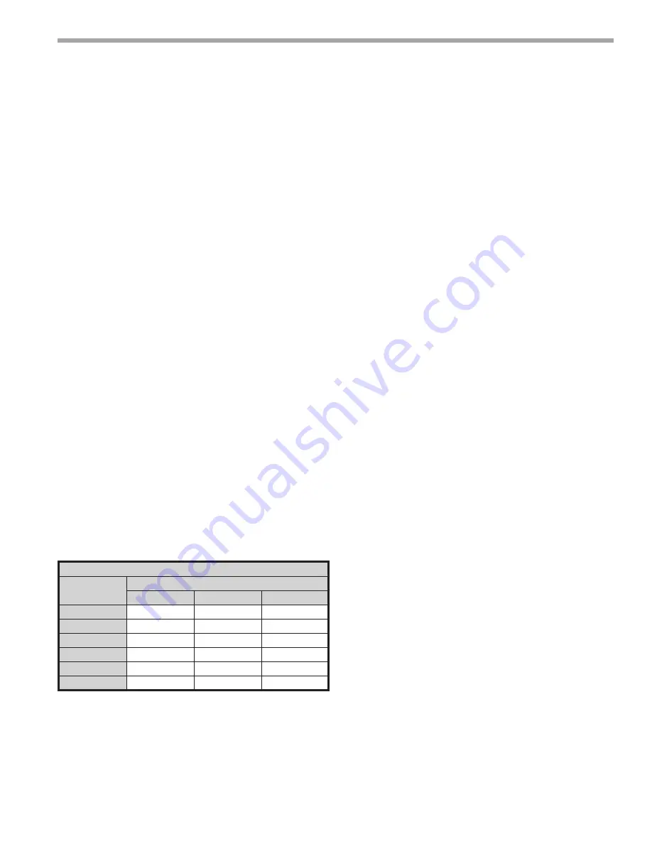
Strainer / Filter Sizing
Mesh Size
Particle Size
Microns
MM
Inch
20
840
0.840
0.0340
30
533
0.533
0.0210
60
250
0.250
0.0100
100
149
0.149
0.0060
150
100
0.100
0.0040
200
74
0.074
0.0029
ppm = parts per million
ppb = parts per billion


