RWF ROTARY SCREW COMPRESSOR UNITS
PROPER INSTALLATION OF ELECTRONIC EQUIPMENT
S70-600 IOM (OCT04)
Page 50
GROUNDING
Grounding is the most important factor for successful op-
eration and is also the most overlooked. The NEC states that
control equipment may be grounded by using the rigid conduit
as a conductor. This worked for the earlier relay systems, but
it is not acceptable for electronic control equipment. Conduit
is made of steel and is a poor conductor relative to a copper
wire. Electronic equipment reacts to very small currents and
must have a good ground in order to operate properly; there-
fore,
copper grounds are required for proper operation.
Note: aluminum may be used for the large three-phase
ground wire.
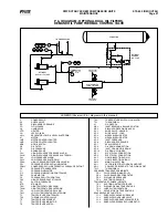
The ground wire must be sized the same size as the
supply wires or one size smaller as a minimum. The
three-phase power brought into the plant must also
have a ground wire,
making a total of four wires. In many
installations that are having electronic control problems, this
essential wire is usually missing. A good ground circuit must
be continuous from the plant source transformer to the elec-
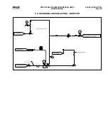
tronic control panel for proper operation. (Figure 41) Driving
a ground stake at the electronic control will cause additional
problems since other equipment in the plant on the same
circuits will ground themselves to the ground stake causing
large ground flow at the electronic equipment.
ALUMINUM
OR COPPER
3-PHASE
BUS
PLANT SUPPLY
TRANSFORMER
COPPER
ELECTRONIC
CONTROL
ART2
Figure 41
WIRING PRACTICES
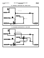
Do not mix wires of different voltages in conduit.
An
example of this would be the installation of a screw com-
pressor package. The motor voltage is 480 volts and the
panel control power is 120 volts.
The 480 volt circuit must
be run from the motor starter to the motor in its own
conduit. The 120 volt circuit must be run from the mo-
tor starter control transformer to the control panel in its
own separate conduit.
If the two circuits are run in the same
conduit, transients on the 480 volt circuit will be inducted
into the 120 volt circuit causing functional problems with the
electronic control. Dividers must be used in wire way systems
(conduit trays) to separate unlike voltages. The same rule
applies for 120 volt wires and 220 volt wires.
Also, never
run low voltage wires in the same conduit with 120 volt
wires.
(Figure 42)
Never run any wires through an electronic control panel
that do not relate to the function of the panel. Electronic
control panels should never be used as a junction box.
These wires may be carrying large transients that will interfere
with the operation of the control. An extreme example of this
would be to run the 480 volts from a motor starter through
the control panel to the motor.
When running conduit to an electronic control panel, take
notice of the access holes (knockouts) provided by the
manufacturer. These holes are strategically placed so that
the field wiring does not interfere with the electronics in the
panel.
Never allow field wiring to come in close proximity
with the controller boards since this will almost always
cause problems.
Do not drill a control panel to locate conduit connec-
tions.
You are probably not entering the panel where the
manufacturer would like you to since most manufacturers
recommend or provide prepunched conduit connections.
Drilling can cause metal chips to land in the electronics
and create a short circuit.
If you must drill the panel, take
the following precautions:
First cover the electronics with
plastic and tape it to the board with masking or electrical tape.
Second, place masking tape or duct tape on the inside of the
panel where you are going to drill. The tape will catch most
of the chips. Then clean all of the remaining chips from the
panel before removing the protective plastic. It would be a
good idea to call the manufacturer before drilling the panel
to be sure you are entering the panel at the right place.
When routing conduit to the top of an electronic control panel,
condensation must be taken into consideration. Water can
condense in the conduit and run into the panel causing cat-
astrophic failure.
Route the conduit to the sides or bottom
of the panel and use a conduit drain.
If the conduit must
be routed to the top of the panel, use a sealable conduit
fitting which is poured with a sealer after the wires have
been pulled, terminated and the control functions have been
checked.
A conduit entering the top of the enclosure must
have an “O” ring-type fitting between the conduit and
the enclosure
so that if water gets on top of the enclosure
it cannot run in between the conduit and the enclosure. This
is extremely important in outdoor applications.
480 VOLT
3-PHASE
BUS
GROUND BUS
ELECTRONIC
CONTROL
120 V
480 V
MOTOR
SEPARATE
CONDUIT
MOTOR
STARTER
PANEL
ART3
Figure 42


