Johnson Controls 6HK Series Installation Manual Download Page 8

Subject to change without notice. Published in U.S.A.

6052931-UAI-A-0121

Copyright © 2021 by Johnson Controls. All rights reserved.

Supersedes: 5181703-UAI-C-0818

York International Corp.

5005 York Drive

Norman, OK 73069

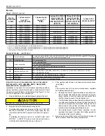
Electric heat kits and operating controls

Low-voltage control connections

T

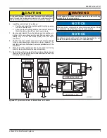
he low-voltage transformer is standard on all models.

The 24-V power supply is provided by an internally wired low-
voltage  transformer,  which  is  standard  on  all  air  handler  and
residential  packaged  unit  models.  Field  supplied  low-voltage
wiring can exit the unit on the top-right corner of the air handler
or the right-side panel of the air handler. See Figure 3 or Figure
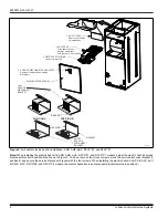
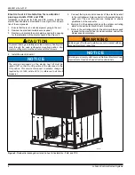
4.  Residential  packaged  unit  models  have  provisions  for  low-
voltage wiring exits in the bottom or right side of the unit. See
Figure  5.  Remove  the  required  knockout  and  pierce  the  foil
faced  insulation  to  allow  the  wiring  to  pass  through.  Use  as
small a hole as possible to minimize air leakage. Install a 7/8-in.
plastic bushing in the selected hole and keep low-voltage wiring
as short as possible inside the control box. To further minimize
air leakage, seal the wiring entry point at the outside of the unit.
Connect  the  field  wiring  at  the  screw  terminals  of  the  control
board  or  on  low-voltage  wiring  leads  using  twist-on  wire  con-
nectors.

NOTICE

For blower speed connections, electrical information and wir-
ing diagrams, see indoor unit installation instructions.

NOTICE

The electric heat kits have both auto resettable and fusible
link thermal limit controls.
If failure occurs, this fusible link thermal limit control must be
replaced with a direct replacement.

NOTICE

All wiring must comply with local and national electrical code
requirements. Read and heed all unit caution labels.

Summary of Contents for 6HK Series

Page 1: ... local building codes or in the absence of local codes with National Electrical Code ANSI NFPA 70 1996 or current edi tion The information contained in this manual is intended for use by a qualified service technician familiar with safety proce dures and equipped with the proper tools and test instru ments Shut OFF electric power at unit disconnect and or service panel before beginning the followi...

Page 2: ... and wiring compartment Table 1 Models covered Electric heat kit kW at 240V 1 phase electric heat kit1 2 all except PHE 1 phase electric heat kit1 2 3 PHE 3 phase 208 V 230 V electric heat kits PHE PCE AHR AHE AHV RFCX E1 RFCX P1 3 Phase 208 V 230 V electric heat kits AP AE AVC AVV RFCX E2 RFCX P2 MP ME MVC 3 phase 460 V electric heat kits4 2 4 6HK 0 1 6500206 6HK 0 1 6500206 4 8 6HK 0 1 6500506 6...

Page 3: ...x on the indoor unit rating plate for the particular electric heat kit installed 10 Refer to the unit rating plate for the minimum blower speed required for the electric heat kit model installed and set the blower speed accordingly CAUTION To prevent damage carefully pass the accessory heating ele ment through the rectangular opening in the discharge duct Element mounting plate must be secured wit...

Page 4: ...h the four screws When installing the electric heat kit in AP AE AVC AVV MP ME MVC RFCX E2 and RFCX P2 models the electric heat kit service disconnect bracket remains in position A Figure 3 Air handler electric heat kit installation AHR AHE AHV RFCX E1 and RFCX P1 2 5 66 3 1 8 7 29 5 5HPRYH IRU KHDWHU NLW LQVWDOODWLRQ 7 5 7 6OLGH KHDWHU LQWR DLU KDQGOHU DQG DWWDFK ZLWK IRXU GXFW FRYHU VFUHZV 6833 ...

Page 5: ...t move the electric heat kit service discon nect bracket to another position Figure 4 Air handler electric heat kit installation AP AE AVC AVV MP ME MVC RFCX E2 and RFCX P2 8 7 29 5 5HPRYH IRU KHDWHU NLW LQVWDOODWLRQ 2 5 66 3 1 6 59 6 211 7 12 2876 5HPRYH LI KHDWHU NLW KDV VHUYLFH GLVFRQQHFWV 7 5 7 6OLGH KHDWHU LQWR DLU KDQGOHU DQG DWWDFK ZLWK IRXU GXFW FRYHU VFUHZV 6833 5 1 RQQHFW WR OHIW VLGH 32...

Page 6: ... on the outdoor unit rating plate for the particular electric heat kit installed 7 Refer to the unit rating plate for the minimum blower speed required for the electric heat kit model installed and set the blower speed accordingly CAUTION To prevent damage carefully pass the accessory heating ele ment through the open rectangular mounting position Ele ment mounting plate must be secured with four ...

Page 7: ... circuits a single point power accessory kit can be ordered separately A ground lug is pro vided on the kits Refer to the unit installation instructions for electrical specifications See Figure 6 and Figure 7 Figure 6 Electric heat kit connection FACTORY WIRING Attached to this side no need for removal TERMINAL BLOCK OR SERVICE DISCONNECTS May have 1 2 or 3 service disconnects FIELD SUPPLIED WIRIN...

Page 8: ...f the unit See Figure 5 Remove the required knockout and pierce the foil faced insulation to allow the wiring to pass through Use as small a hole as possible to minimize air leakage Install a 7 8 in plastic bushing in the selected hole and keep low voltage wiring as short as possible inside the control box To further minimize air leakage seal the wiring entry point at the outside of the unit Conne...

Reviews: