


6052931-UAI-A-0121
4
Johnson Controls Ducted Systems
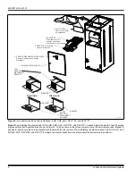
Note:
When installing the electric heat kit in AHR, AHE, AHV, RFCX*E1, and RFCX*P1 models, adjust the electric heat kit service
disconnect bracket to position B as shown in Figure 3. To do so, remove four mount screws, move the service disconnect bracket to
position B, and secure the service disconnect bracket with the four screws. When installing the electric heat kit in AP, AE, AVC, AVV,
MP, ME, MVC, RFCX*E2, and RFCX*P2 models, the electric heat kit service disconnect bracket remains in position A.
Figure 3:
Air handler electric heat kit installation - AHR, AHE, AHV, RFCX*E1, and RFCX*P1
%/2:(5$&&(663$1(/
$
'8&7&29(5
5HPRYHIRUKHDWHU
NLWLQVWDOODWLRQ
+($7(5.,7
6OLGHKHDWHULQWRDLU
KDQGOHUDQGDWWDFK
ZLWKIRXUGXFWFRYHUVFUHZV
),(/'6833/<:,5,1*
&RQQHFWWROHIWVLGH
6(59,&(',6&211(&7.12&.2876
5HPRYHLIKHDWHUNLWKDVVHUYLFH
GLVFRQQHFW
326,7,21$
326,7,21%
%5$&.(7
%5$&.(7
%5$&.(7
6+257
6(59,&(
',6&211(&7
%5$&.(7
7$//
6(59,&(
',6&211(&7
%5$&.(7


