


6052931-UAI-A-0121
Johnson Controls Ducted Systems
7
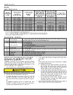
Line power connections
Power can be brought into the air handler through the outlet air
end of the unit (top left when the unit is vertical) or the left-side
panel. For the residential packaged unit, power can be brought
into the electric/controls area through the power supply provi-
sions in the bottom or right side of the unit. To minimize air leak-
age for any unit, seal the field wiring entry point.
Field wiring connects to electric heat kits with service discon-
nect or terminal block depending on the electric heat kit model.
The multiple circuit, single-phase electric heat kits have options
for a single power supply. For the 3 phase 20 kW and 25 kW
electric heat kits with multiple circuits, a single-point power
accessory kit can be ordered separately. A ground lug is pro-
vided on the kits. Refer to the unit installation instructions for
electrical specifications. See Figure 6 and Figure 7.
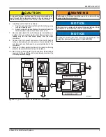
Figure 6:
Electric heat kit connection
FACTORY WIRING
Attached to this side -
no need for removal.
TERMINAL BLOCK OR
SERVICE DISCONNECTS
May have 1, 2, or 3 service disconnects.
FIELD SUPPLIED WIRING
Attaches to left side.
A0241-001
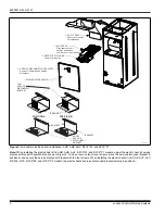
Figure 7:
Air handler and residential packaged unit electric heat power
),(/'32:(5:,5,1*
9WKUX9RU9
&20321(17&2'(6
*1'*5281'/8*
6'6(59,&(',6&211(&7
&.7&,5&8,7
*1'
-803(5%$5
6,1*/(6285&(32:(5
08/7,6285&(32:(5
6,1*/(6285&(32:(5
:,7+-803(5%$5
6'
32:(5
6833/<
/
/
7(50,1$/%/2&.25
6(59,&(',6&211(&7
32:(5
6833/<
*1'
/
/
6,1*/(6285&(32:(5
7(50,1$/%/2&.25
6(59,&(',6&211(&7
*1'
32:(5
6833/<
/
/
/
&.7
&.7
32:(5
6833/<
6'
6'
*1'
/
/
/
/
/
/
08/7,6285&(32:(5
32:(5
6833/<
&,5&8,7621.:.:
&,5&8,7621.:
*1'
/
/
/
/
/
/
&.7
6'
6'
6'
&.7
&.7
&,5&8,7621.:.:
&,5&8,7621.:
6,1*/(3+$6((/(&75,&+($7237,216
7+5((3+$6((/(&75,&+($732:(5237,216
$
6,1*/(6285&(32:(5
:,7+6,1*/(32,17
32:(5$&&(6625<
32:(5
6833/<
6'
*1'
/
/
/
/
/
/
6'
/
/
/
6'
6'


