background image

175619-XIM-C-0109

30

Johnson Controls Unitary Products

ECONOMIZER WITH SINGLE ENTHALPY SENSOR -

When the room thermostat calls for cooling, the low
voltage control circuit from “R” to “G” and “Y1” is com-
pleted. The UCB energizes the blower motor (if the fan
switch on the room thermostat is set in the “AUTO”
position) and drives the economizer dampers from fully
closed to their minimum position. If the enthalpy of the
outdoor air is below the setpoint of the enthalpy con-
troller (previously determined), “Y1” energizes the
economizer. The dampers will modulate to maintain a
constant supply air temperature as monitored by the
discharge air sensor. If the outdoor air enthalpy is
above the setpoint, “Y1” energizes the compressor and
condenser fan motor only.

Once the thermostat has been satisfied, it will de-ener-
gize “Y1”. If the compressor has satisfied its minimum
run time, the compressor and condenser fan are de-
energized. Otherwise, the unit operates the cooling
system until the minimum run times for the compressor
has been completed. After the compressor de-ener-
gizes, the blower is stopped following the elapse of the
fan off delay for cooling, and the economizer damper
goes to the closed position. If the unit is in continues
fan operation the economizer damper goes to the min.
position.

ECONOMIZER WITH DUAL ENTHALPY SENSORS - 

The operation with the dual enthalpy sensors is identi-
cal to the single sensor except that a second enthalpy
sensor is mounted in the return air. This return air sen-
sor allows the economizer to choose between outdoor
air and return air, whichever has the lowest enthalpy
value, to provide maximum operating efficiency.

ECONOMIZER (SINGLE OR DUAL) WITH POWER 
EXHAUST - 

This system operates as specified above with one
addition. The power exhaust motor is energized 45
seconds after the actuator position exceeds the
exhaust fan setpoint on the economizer control. When
the power exhaust is operating, the second stage of
mechanical cooling will not operate. As always, the “R”
to “G” connection provides minimum position but does
not provide power exhaust operation.

MOTORIZED OUTDOOR AIR DAMPERS - 

This system operation is the same as the units with no
outdoor air options with one exception. When the “R” to
“G” circuit is complete, the motorized damper drives

open to a position set by the thumbwheel on the
damper motor. When the “R” to “G” circuit is opened,
the damper spring returns fully closed.

COOLING OPERATION ERRORS

Each cooling system is monitored for operation outside
of the intended parameters. Errors are handled as
described below. All system errors override minimum
run times for compressors.

HIGH-PRESSURE LIMIT SWITCH

During cooling operation, if a high-pressure limit switch
opens, the UCB will de-energize the compressor, initi-
ate the ASCD (Anti-short cycle delay), and, stop the
condenser fan. If the call for cooling is still present at
the conclusion of the ASCD, the UCB will re-energize
the compressor.

Should a high-pressure switch open three times within
two hours of operation, the UCB will lock-out the com-
pressor and flash a code (see Table 8).

LOW-PRESSURE LIMIT SWITCH

The low-pressure limit switch is not monitored during
the initial 30 seconds of a cooling system's operation.
For the following 30 seconds, the UCB will monitor the
low-pressure switch to ensure it closes. If the low-pres-
sure switch fails to close after the 30-second monitor-
ing phase, the UCB will de-energize the compressor,
initiate the ASCD, and stop the condenser fan.

Once the low-pressure switch has been proven (closed
during the 30-second monitor period described above),
the UCB will monitor the low-pressure limit switch for
any openings. If the low-pressure switch opens for
greater than 5 seconds, the UCB will de-energize the
compressor, initiate the ASCD, and stop the condenser
fan.  

If the call for cooling is still present at the conclusion of
the ASCD, the UCB will re-energize the compressor.

Should a low-pressure switch open three times within
one hour of operation, the UCB will lock-out the com-
pressor and flash a code (see Table 8). 

FREEZESTAT

During cooling operation, if a freezestat opens, the
UCB will de-energize the compressor, initiate the
ASCD, and stop the condenser fan. If the call for cool-

Summary of Contents for SUNLINE 2000 BQ 036

Page 1: ...ODUCT NOMENCLATURE 6 INSTALLATION 7 OPERATION 29 START UP COOLING 33 TROUBLESHOOTING 33 MAINTENANCE 37 See the following page for a complete Table of Con tents NOTES CAUTIONS AND WARNINGS Installer sh...

Page 2: ...BLOWERS 27 CHECKING SUPPLY AIR FLOW RATE 27 OPERATION 29 SEQUENCE OF OPERATIONS OVERVIEW 29 COOLING SEQUENCE OF OPERATION 29 CONTINUOUS BLOWER 29 INTERMITTENT BLOWER 29 NO OUTDOOR AIR OPTIONS 29 ECONO...

Page 3: ...S Tbl Pg 1 UNIT APPLICATION DATA BQ 7 2 CONTROL WIRE SIZES 12 3 ELECTRIC HEATER SUPPLY AIRFLOW LIMITATIONS 13 4 BQ 4 POINT LOADS WEIGHT DISTRIBUTION KG LBS 17 5 BQ 6 POINT LOADS WEIGHT DISTRIBUTION KG...

Page 4: ...hould install repair main tain or service this equipment Observe all precautions in the literature on labels and tags accompanying the equipment whenever working on air conditioning equipment Be sure...

Page 5: ...ARNING Notes are intended to clarify or make the installation easier Cautions are given to prevent equipment damage Warnings are given to alert installer that personal injury and or equip ment damage...

Page 6: ...ohnson Controller DFS APS Honeywell Controller DFS APS Novar Controller DFS APS Simplicity IntelliComfort Controller Simplicity IntelliComfort Controller w ModLinc 2 Pleated filters BAS Ready Economiz...

Page 7: ...er s and or the customer s expense Size of unit for proposed installation should be based on heat loss heat gain calculation made according to the methods of the Air Conditioning Contractors of Americ...

Page 8: ...the unit Do not remove any packaging until the unit is near the place of installa tion Rig the unit by attaching chain or cable slings to the lifting holes provided in the base rails Spreader bars wh...

Page 9: ...should NOT be sized to match the dimensions of the duct connections on the unit Refer to Figures 7 and 10 for information concerning side and bottom supply and return air duct openings CONDENSATE DRAI...

Page 10: ...l result in frosted coils or safety shutdown Minimum filter area and required sizes are shown in Physical Data Table 8 SERVICE ACCESS The following removable panels provide access to all serviceable c...

Page 11: ...CONTROL TERMINAL BLOCK TERMINALS ON A LIMITED NUMBER OF THERMOSTATS 3 1 2 4 3 1 2 4 Second stage heating not required on single stage heating units Second stage cooling not required on single stage c...

Page 12: ...ment wire must be of the type shown on the wiring diagram and the same mini mum gauge as the replaced wire Electrical line must be sized properly to carry the load Use copper conductors only Each unit...

Page 13: ...e Minimum Position Adjusting screw found on the damper control module fully clockwise and then set the thermostat indoor fan switch to the on position and then off or energize and de energize terminal...

Page 14: ...the signal is below it s setpoint the actuator is allowed to modulate normally in accor dance with the enthalpy and mixed air sensor inputs When the AQ signal exceeds it s setpoint setting and there i...

Page 15: ...175619 XIM C 0109 Johnson Controls Unitary Products 15 FIGURE 4 ENTHALPY SETPOINT ADJUSTMENT...

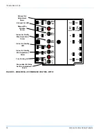
Page 16: ...IAQ IAQ Min Free Cool T T1 AQ1 AQ SO SO SR SR A B C D TR TR1 24 Vac HOT 24 Vac COM EF EF1 2 3 4 5 1 Exhaust Air Adjustment Screw Exhaust Air LED Damper Min Position Screw Indoor Air Quality Max Adjust...

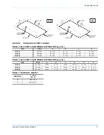
Page 17: ...TRIBUTION kg Lbs UNIT TOTAL A B C D E F BQ036 252 555 37 82 37 81 36 80 46 102 47 104 48 105 BQ048 270 595 40 88 40 87 39 86 50 110 50 111 51 112 BQ060 281 620 42 92 41 91 41 90 52 114 52 116 53 117 1...

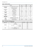
Page 18: ...4200 4500 CONDENSER COILS Rows Deep 1 1 1 Fins Per Inch 25mm 20 20 20 Face Area m2 ft2 1 60 17 1 1 60 17 1 1 60 17 1 COMPRESSOR Qty Per Unit Type Quantity Reciprocating 1 Reciprocating 1 Scroll 1 AIR...

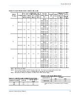
Page 19: ...7 5 10 4 29 5 35 2CE045115462 10 2 14 2 34 2 40 2CE045120462 14 6 20 3 41 9 45 2CE045130462 21 5 29 9 53 9 60 Note 1 HACR Type per NEC Note 2 These electric heaters DO NOT include a fuse box If a fuse...

Page 20: ...S 3 5 TON HEAT PUMP FRONT VIEW FIGURE 8 UNIT WITH ECONOMIZER RAINHOOD 829 325 8 1140 447 8 64 21 2 213 83 8 292 111 2 445 171 2 445 171 2 181 77 8 171 63 4 206 81 8 137 53 8 2089 821 4 165 61 2 mm inc...

Page 21: ...ED OUTDOOR AIR MOTORIZED DAMPER RAINHOOD FIGURE 10 UNIT DIMENSIONS REAR VIEW DETAIL B 454 177 8 184 71 4 699 271 2 485 191 8 1140 447 8 305 12 419 161 2 mm inch 260 101 4 89 31 2 210 81 4 111 43 8 mm...

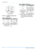
Page 22: ...FOR DICONNECT SWITCH Shipped attached to the blower housing inside the blower compartment FIELD SUPPLIED DISCONNECT SWITCH LOCATION BLOWER MOTOR ACCESS FILTER ACCESS DOT PLUGS TABLE 14 MINIMUM CLEARAN...

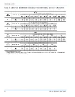
Page 23: ...70 750 1440 725 1410 700 1370 675 1330 650 CFM WATTS CFM WATTS CFM WATTS CFM WATTS HI 1600 765 1540 735 1490 700 1380 670 MED 1450 690 1400 665 1360 650 1270 610 LOW 1290 625 1250 610 1220 600 1130 56...

Page 24: ...800 LOW 1635 810 1610 780 1580 760 1555 740 1540 730 CFM WATTS CFM WATTS CFM WATTS CFM WATTS HI 1840 910 1770 825 1660 825 1530 775 MED 1620 775 1560 740 1480 700 1390 660 LOW 1510 715 1460 690 1400 6...

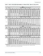
Page 25: ...1405 1054 1470 1074 1525 1094 1560 1116 1595 1140 1620 1167 1640 2300 1005 1260 1024 1275 1049 1370 1069 1440 1090 1475 1116 1505 1142 1535 2200 980 1160 1002 1170 1022 1190 1044 1250 1066 1350 1090 1...

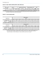
Page 26: ...15KW 0 04 0 05 0 06 0 07 0 08 0 10 0 12 0 14 0 16 20 30KW 0 06 0 07 0 08 0 09 0 11 0 13 0 15 0 17 0 20 0 06 0 07 0 08 0 09 0 10 0 11 0 12 0 14 0 16 BOTTOM DUCT CONNECTIONS1 ELECTRIC HEATERS1 RESISTAN...

Page 27: ...st be within the limitations shown in the Unit Application Data Table 1 2 Pulleys can be adjusted in half turn increments 3 The tension on the belt should be adjusted as shown in the Belt Adjustment F...

Page 28: ...atly measuring the pressure drop across a wet coil under field conditions would be inaccurate To assure a dry coil the compressors should be deac tivated while the test is being run 4 Knowing the pres...

Page 29: ...the system switch set to either the AUTO or HEAT settings the blower is energized whenever a cooling or heating operation is requested The blower is ener gized after any specified delay associated wit...

Page 30: ...ion provides minimum position but does not provide power exhaust operation MOTORIZED OUTDOOR AIR DAMPERS This system operation is the same as the units with no outdoor air options with one exception W...

Page 31: ...low pressure switch to protect against loss of refrigerant charge opens at 48 kPa gauge 7 psig and resets at 154 kPa gauge 22 psig The above pressure switches are hard soldered to the unit The refrige...

Page 32: ...umper across the test pin terminals on the board Depending on the selected defrost minimum run time of 30 60 or 90 minutes the board will go into defrost in 7 5 15 or 22 5 seconds The DC will remain i...

Page 33: ...essures 2 Measure the temperature drop across the evapora tor coil 3 Measure the system Amperage draw across all legs of 3 phase power wires 4 Measure the condenser fan amp draw SHUT DOWN 1 Set the th...

Page 34: ...room thermostat and the UCB c Loose wiring from the room thermostat to the UCB 9 If 24 volts is present at the room thermostat but not at the UCB check for proper wiring between the thermostat and th...

Page 35: ...4 volts is pres ent at the Y1 OUT terminal check for 24 volts at the Y1 ECON terminal If 24 volts is not present check for loose wiring from the Y1 OUT terminal to the Mate N Lock plug the jumper in t...

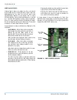
Page 36: ...second span the fault history is cleared TEST RESET When this button is pressed and released one time within five seconds any anti short cycle delays ASCD is by passed for one cycle When this button i...

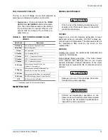
Page 37: ...cation of the motor and bearings can extend the life of components but is optional TABLE 8 UNIT CONTROL BOARD FLASH CODES Flash Code Description On Steady Control Failure Replace Control Heart Beat No...

Page 38: ...otor for ten minutes until excess grease is purged from the cavity Replace the plugs 5 ton units are supplied with blower shaft bearings that do not require maintenance but may be lubricated if desire...

Page 39: ...175619 XIM C 0109 Johnson Controls Unitary Products 39...

Page 40: ...hange without notice Printed in U S A 175619 XIM C 0109 Copyright 2009 by Unitary Products Group All rights reserved Supersedes 175619 YIM B 0507 Johnson Controls Unitary Products 5005 York Drive Norm...

Reviews: