


- Page 14 -
1.6 GENERAL
CAUTIONS
A. DURING THE USE AND MAINTENANCE OF THE MA-
CHINE IT IS MANDATORY TO COMPLY WITH ALL LAWS
AND REGULATIONS FOR ACCIDENT PREVENTION.
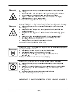
B. THE ELECTRICAL POWER SOURCE MUST HAVE A
GROUND CABLE AND THE GROUND CABLE OF THE
MACHINE MUST BE CONNECTED TO THE GROUND
CABLE OF THE POWER SOURCE.
C. BEFORE ANY MAINTENANCE OR REPAIRS ARE AC-
COMPLISHED THE MACHINE MUST BE DISCONNECTED
FROM THE AIR AND ELECTRICAL SUPPLY.
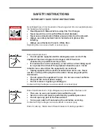
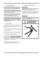
D. NEVER WEAR TIES, CHAINS OR OTHER LOOSE
ARTICLES WHEN USING, MAINTAINING OR REPAIR-
ING THE MACHINE. LONG HAIR IS ALSO DANGEROUS
AND SHOULD BE KEPT UNDER A HAT. THE USER MUST
WEAR PROPER SAFETY ATTIRE - GLOVES, SAFETY
SHOES AND GLASSES.
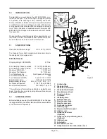
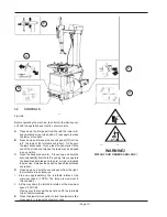
2.0 INSTALLATION
Your new JBC EEWH553A Tire Changer requires a simple
installation procedure requiring only a few moments. Fol-
low these instructions carefully to insure proper and safe
operation.
The Tire Changer is delivered mounted to a wooden skid.
Remove tire changer from its mounts carefully, taking care
to avoid any back strain.
Place Changer where proper operation will be unobstructed
to all sides. Install the machine in a covered and dry place.
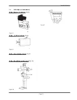
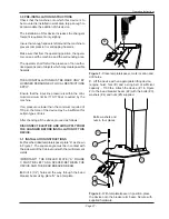
2.0.1 Models with SRA attached (Optional)
Once placed in the desired location the tire changer must be
bolted to the fl oor using only the rear two mounting holes.
Mounting anchors are provided with those machines with a
Safety Restraint Arm. Concrete must be a minimum of four
inches commercial grade, 3500-4000 PSI, with a cure time
of at least 28 days. Steel mesh reinforced.
Tire Changer must be anchored to concrete fl oor
if equipped with a “Safety Restraint Arm”
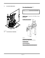
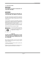
2.1
ELECTRICAL INSTALLATION
BUILDING ELECTRICAL INSTALLATION MUST BE
MADE BY A LICENSED ELECTRICIAN.
Check that the electrical specifi cations of the power source
are the same of the machine. The machine uses 230v, 60
hz, single phase 12 amp source. Electric specifi cations are
clearly marked on a label at the rear of the machine.
FAILURE TO PROVIDE PROPER ELECTRICAL SUP-
PLY AND GROUNDING WILL CREATE A SHOCK
HAZARD TO THE OPERATOR.
540
Summary of Contents for EEWH553A Series
Page 1: ...High Performance Tire Changer Operation Instructions Form ZEEWH553AE ...
Page 2: ... BLANK PAGE ...
Page 4: ... BLANK PAGE ...
Page 30: ... BLANK PAGE ...
Page 31: ... BLANK PAGE ...


