


CLIZIA D 24 AS
16
EN
cod. 3541C810 - Rev. 00 - 09/2012
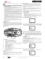
4. SERVICE AND MAINTENANCE
4.1 Adjustments
Gas conversion
The unit can operate on natural gas or LPG and is factory-set for use with one of these
two gases, as clearly shown on the packing and on the dataplate. Whenever a gas dif-
ferent from that for which the unit is arranged has to be used, the special conversion kit
will be required, proceeding as follows:
1.
Replace the nozzles at the main burner, fitting the nozzles specified in the technical
data table in cap. 5, according to the type of gas used
2.
Modify the parameter for the type of gas:
•
put the boiler in standby mode
•
press the DHW buttons (details 1 and 2 - fig. 1) for 10 seconds: the display
shows “
b01
“ blinking.
•
Press the DHW buttons (details 1 and 2 - fig. 1
) to set parameter 00
(for natural
gas operation) or
01
(for LPG operation).
•
press the DHW buttons (details 1 and 2 - fig. 1) for 10 seconds.
•
the boiler will return to standby mode
3.
Adjust the minimum and maximum pressures at the burner (ref. relevant para-
graph), setting the values given in the technical data table for the type of gas used
4.
Apply the sticker contained in the conversion kit, near the dataplate as proof of the
conversion.
TEST mode activation
Press the heating buttons (details 3 and 4 - fig. 1) together for 5 seconds to activate the
TEST
mode. The boiler lights at the maximum heating power set as described in the fol-
lowing section.
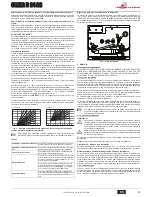
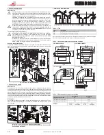
The heating and DHW symbols (fig. 17) flash on the display; the heating power will ap-
pear alongside.
fig. 17 - TEST mode (heating power = 100%)
Press the heating buttons (details 3 and 4 - fig. 1) to increase or decrease the power
(Min.=0%, Max.=100%).
By pressing the DHW
“-”
button (detail 1 - fig. 1), boiler output is immediately adjusted
to min. (0%). By pressing the DHW
“+”
button (detail 2 - fig. 1), boiler output is immedi-
ately adjusted to max. (100%).
If the TEST mode is activated and enough hot water is drawn to activate the DHW mode,
the boiler remains in TEST mode but the 3-way valve goes to DHW.
To deactivate the TEST mode, press the heating buttons (details 3 and 4 - fig. 1) together
for 5 seconds.
The TEST mode is automatically deactivated in any case after 15 minutes or on stopping
of hot water drawing (if enough hot water has been drawn to activate the DHW mode).
Pressure adjustment at the burner
Since this unit has flame modulation, there are two fixed pressure settings: minimum and
maximum, which must be those given in the technical data table according to the type of
gas.
•
Connect a suitable pressure gauge to the pressure point
"B"
downstream of the
gas valve.
•
Activate the TEST mode (see cap. 4.1).
•
Press the Eco/Comfort button for 2 seconds to access the gas valve Calibration
mode.
•
The card goes to the setting “q02”; displaying the actually saved value, by pressing
the DHW buttons .
•
If the pressure gauge reading is different from the nominal maximum pressure, pro-
ceed by increases/decreases of 1 or 2 units of parameter “q02” by pressing the
DHW buttons : the value is stored after each modification; wait 10 seconds for the
pressure to stabilise.
•
Press the heating button “-” (ref. 3 - fig. 1).
•
The card goes to the setting “q01”; displaying the actually saved value, by pressing
the DHW buttons .
•
If the pressure gauge reading is different from the nominal minimum pressure, pro-
ceed by increases/decreases of 1 or 2 units of parameter “q01” by pressing the
DHW buttons : the value is stored after each modification; wait 10 seconds for the
pressure to stabilise.
•
Recheck both adjustments by pressing the heating buttons and adjust them if nec-
essary by repeating the above procedure.
•
Press the Eco/Comfort button for 2 seconds to return to the TEST mode.
•
Deactivate the TEST mode (see cap. 4.1).
•
Disconnect the pressure gauge.
Heating power adjustment
To adjust the heating power, switch the boiler to TEST mode (see sec. 4.1). Press the
heating buttons (detail 3 - fig. 1) to increase or decrease the power (min. = 00 - max. =
100). Press the
reset
button within 5 seconds and the max. power will remain that just
set. Exit TEST mode (see sec. 4.1).
Configuration Menu
Press the DHW buttons together for 10 seconds to access the configuration Menu. 7 pa-
rameters are available, indicated by the letter "b", which are not modifiable from Remote
Timer Control.
Press the Heating buttons to scroll the list of parameters in increasing or decreasing or-
der. Press the DHW buttons to view or modify the value of a parameter: the modification
will be automatically saved.
0
1
4
2
3
reset
eco
comfort
II
II
II
I I
I I I I I I
II
II
II
II
II
II
II
I I
I I I I I I
II
II
II
II
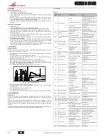
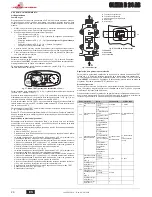
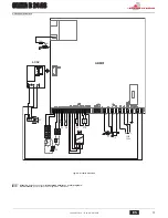
fig. 18 - Gas valve
A
- Upstream pressure point
B
- Downstream pressure point
I
- Gas valve electrical connection
R
- Gas outlet
S
- Gas inlet
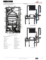
fig. 19 - Gas valve connection
TYPE SGV100
Pi max 65 mbar
24 Vdc - class B+A
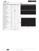
Contents Description
Range
Default
CLIZIA D 24 AS
b01
Gas type selection
0=Natural Gas
0=Natural Gas
0=Natural Gas
1=LPG
b02
Boiler type selection
1=Bithermal instantane-
ous
1=Bithermal instantane-
ous
2=Monothermal instanta-
neous
2=Monothermal instanta-
neous
3=Heating only (3-way
valve)
4=Heating only (circulat-
ing pump)
b03
Combustion chamber
type selection
0=Sealed Chamber com-
bustion control
(without fume pressure
switch)
0=Sealed Chamber with
combustion control
0=Sealed Chamber with
combustion control
(without fume pressure
switch)
1=Open Chamber (with
fume thermostat)
2=Sealed Chamber (with
fume pressure switch)
3=Sealed Chamber com-
bustion control
(with fume thermostat on
recuperator)
4=LOW NOx Sealed
Chamber combustion
control
(without fume pressure
switch)
5=LOW NOx Open
Chamber
(with fume thermostat)
b04
Primary Exchanger type
selection
(b03=0)
0=Flat
0=Flat
0=Flat
1=Omega
2=--
No effect on adjustment
(b03=1)
--
0
No effect on adjustment
(b03=2)
--
0
Primary Exchanger type
selection
(b03=3)
0=Flat
0=Flat
1=Omega
2=--
No effect on adjustment
(b03=4)
--
0
No effect on adjustment
(b03=5)
--
0
R
B
I
A
S
~ 65
Ω
~ 24
Ω
Summary of Contents for Clizia 24 AS
Page 43: ......