background image

III

touch the surface to avoid scald.

CE  certification  marks.  It  means  that  inverter  complies  with  the

requirement of CE certification.

Summary of Contents for JNP1K1L-V5

Page 1: ...User Manaul Solar Pumping Inverter JNP550L V5 JNP750L V5 JNP1K1L V5 JNP1K5L V5 JNP2K2L SE V5 JNP2K2L SE V5 EN V1 0 ...

Page 2: ...ential information about Solar pumping inverter of Supplier It strictly prohibited to disclose the document by duplicating photocopying publishing online and in other forms without supplier s permission Supplier reserves the right to change details in this publication without notice ...

Page 3: ... each type of inverter in details Target Reader This manual applies to the professional engineering and technical person who is responsible for installing and operating of inverter and LCD panel Use the Manual Please read this manual carefully before installing and operating inverter Please keep this manual well for operation and maintenance in future The manual content would be constantly updated...

Page 4: ...part of the business interruption if safety warning is ignored Note Means that the content is additional information Inverter related symbols Symbol Meaning Direct current DC Alternating current AC Protective grounding Refer to relevant instructions Can not discard inverter together with domestic garbage Beware of dangerous high voltage Should wait for 5 minutes after inverter and PV panel are dis...

Page 5: ...III touch the surface to avoid scald CE certification marks It means that inverter complies with the requirement of CE certification ...

Page 6: ...YSTEM INTRODUCTION 5 2 2 PRODUCT S INTRODUCTION 7 2 2 1 Appearance 7 2 2 2 Production Dimensions 9 2 2 3 Product Name 10 3 INVERTER UNPACKING 11 3 1 UNPACKING CHECK 11 3 2 IDENTIFY INVERTER 12 4 INSTALLATION PROCEDURE 14 4 1 PREPARE INSTALLATION TOOLS 14 4 2 INSTALLATION STEPS 14 5 INSTALLATION 16 5 1 INSTALLATION SITE REQUIRED 16 5 2 INSTALLATION DIRECTION 17 ...

Page 7: ...nection 31 6 7 COMMUNICATION CONNECTION 34 6 7 1 RS485 Communication 34 6 7 2 GPRS Communication 36 6 8 DISASSEMBLING 36 6 8 1Safety Instruction 36 6 8 2 Disassembling of Connector 37 7 COMMISSIONING 38 7 1 VERIFY BEFORE COMMISSIONING 38 7 2 INVERTER COMMISSIONING 38 7 3 STOP FREQUENCY SETTING 41 8 LCD PANEL OPERATING INSTRUCTIONS 43 8 1 INVERTER LCD DISPLAY 43 8 1 1 LED Indicator Direction 43 8 1...

Page 8: ...sic Information 49 8 3 1 4 Statistic Information 50 8 3 3 Information inquiry 58 8 3 4 Parameter Setting 60 9 MALFUNCTION AND TROUBLESHOOTING 64 9 1 TROUBLESHOOTING 64 9 2 MAINTENANCE 72 9 3 CONTACT CUSTOMER SERVICE 73 10 APPENDIX A 74 11 APPENDIX B 76 11 1 QUALITY ASSURANCE 76 11 2 CONTACT US 77 ...

Page 9: ...rning All the installation and operation of JNPxL series Solar pumping inverter must be completed by professional and technical person Professional and technical person need Receive special training Read this manual completely and master the operation related to safety matters Any damage caused by improper installation or operation which do not according to the introduction in this manual will be ...

Page 10: ...l connections Danger Ensure that the solar cell array should be covered by light tight materials before electrical connecting otherwise the solar cell array would produce high voltage under the sun to cause casualties Warning All the operation and wiring work should be operated by professional electrical or mechanical engineer Please do not close switch on breakers before all the equipments are no...

Page 11: ...e inverter may be caused non recoverable damage Ensure that the open circuit voltage of JNPxL shall not exceed 450V when configuring PV arrays otherwise inverter may be caused non recoverable damage It would influence the machine features and may cause machine damage if the installation environment is selected improperly Do not install the inverter in inflammable explosive place or inflammable exp...

Page 12: ...screen and DC electrical connecter can be touched when the inverter is running the heating devices such as radiator etc should not be touched to avoid scald Maintenance Danger Maintenance should be done by professional maintenance technical person Please ensure that AC side breakers should be turned off firstly then DC side breakers should be turned off before checking and maintaining after waitin...

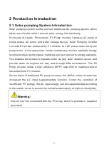
Page 13: ... and adjust pump speed matching energy required to energy available This enables the system to operate under varying solar isolation levels and provide water throughout the day and through different seasons The PV Pump Inverter utilize a high efficiency MPPT algorithm to maximize power harvested from PV module On the basis of traditional PV pump inverters the JNPxL series inverter has increased th...

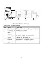
Page 14: ... A PV array Monocrystalline silicon or Polycrystalline silicon B Grid power or Diesel Generator Single phase AC power C Solar pumping inverter NP550L V5 JNP750L V5 JNP1K1L V5 JNP1K5L V5 JNP2K2L SE V5 D AC pump Single phase or three phase AC pump E Water storage device Can be the reservoir fields and etc ...

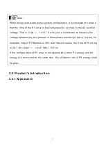
Page 15: ...imeter to measure the voltage between any two phases in three phase electricity that is U wire for example Vmp of PV Module is 30V and 18pcs in series the Vmp of PV string is 30 18 540V 1 414 380 537 3v If the configuration of PV array is not appropriate when PV energy and AC energy are connected at the same time the utilization rate of PV energy shall be poor 2 2 Product s Introduction 2 2 1 Appe...

Page 16: ...play screen also can set some function and parameters of inverter 2 Connection terminals Including DC input terminal PV PV AC input terminal AC in output terminal MOTOR sensor connection terminal SERSOR communication COM terminal 3 Machine serial No Machine factory number when need after sales service should provide the number 4 Nameplate Inverter basic parameters listed on the nameplate for basic...

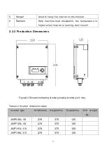
Page 17: ...igher when inverter is running don t touch 2 2 2 Production Dimensions Figure2 3 Dimension drawing of solar pumping inverter unit mm Table2 3 Inverter dimension table Inverter type Width mm Height mm Depth mm Net weight kg JNP550L V5 278 370 125 JNP750L V5 278 370 125 JNP1K1L V5 278 370 125 JNP1K5L V5 278 370 125 ...

Page 18: ...10 JNP2K2L SE V 5 278 370 125 6 3 2 2 3 Product Name The way of product naming take JNP2K2L for example H 380V L 220V Power level JN P 2K2 L Company name Product series name ...

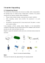
Page 19: ...e check whether the equipment is in good condition According to the packing list to check whether all the parts is correct and in good condition If any damage is found please contact Supplier or the transportation company Please keep well the photos taken at the damaged parts and we ll provide you with best and fastest services Supplier supply the standard inverter and some commonly used accessori...

Page 20: ...Cold pressed terminal SC6 5 Standard 5 Expansion bolt M6 60 Standard 6 Water level sensor B Optional 7 Quick Installation Guideline Standard 8 Packing list Standard 9 Water level sensor A Optional 10 Certificate of inspection Standard 3 2 Identify Inverter The nameplate in the side of inverter and it shows the inverter model some important parameter and certificate mark ...

Page 21: ...nformation table NO Description 1 Inverter name and model 2 Inverter parameter information 3 Certificate and safety signs concrete meaning please refer to Preface 4 Inverter factory number Note Photos are for reference only please adhere to the original products ...

Page 22: ...ommend specification Function Wire crimpers M2 5 M8 Used for PV connector wire core pressure welding Electric drill Ф8 Used for inverter installation plate fixed hole drilling Straight screwdriver Ф3 Used for the AC wire installation Cross screwdriver Ф5 Used for disassembling inverter cover Inner hexagon spanner 5 Used for disassembly and assembly of inverter coverer 4 2 Installation Steps Tools ...

Page 23: ...arts are complete 4 1 Whether the installation environment meets the requirements 1 2 Read the manual especially the Safety Instructions 1 3 Choose the best installation location 5 1 Installation 5 3 4 Electrical connection 6 Select cables 6 3 AC side wire connection 6 4 DC side wire connection 6 5 Sensor wire connection 6 6 Communication wire connection 6 7 5 Commissioning 7 6 Configuration param...

Page 24: ...e inverter in the closed case otherwise the inverter will not work properly Inverter protection level is IP65 can be installed outdoor when the inverter is installed outdoor should be installed as far as possible in the eaves or other have the shadow place avoiding direct sunlight rain and snow Inverter is installed indoor keep away from windows avoiding lightning The installation place selected s...

Page 25: ...er should be convenient for operation and reading out of the LCD displayed information Do not install the inverter in a place where children can touch The inverter uses air cooling mode and the installation site selected should ensure the minimum installation spacing between the inverter and the fixed object and the nearby inverters to ensure an good ventilation And in front of the inverter need t...

Page 26: ...Minimum spacing of adjacent installations Table5 1 Minimum spacing dimension Direction Minimum spacing Above 100cm Below 100cm Sides 100cm Front 100cm 5 3 Installation of Inverter Note Do not use jacking bolts and screws install inverters on rocks or panel ...

Page 27: ...table bolt to finish the installation the bolt length should be enough and penetrate the 1 2 depth of the walls Figure5 3 JNPxL Mounting hole bitmap Step1 According to the size of the inverter select a suitable position on the wall and it is recommended to drill 8 1 0mm in diameter 60 5 0mm in depth and 210mm in spacing Drive the expansion bolt into the hole ...

Page 28: ...allation of expansion bolts Figure5 5 Installation completed renderings Step2 Fasten the inverter lug through the expansion bolt and fix it in the positioned hole Step3 Tighten the bolts make the bolts cling to the wall ...

Page 29: ...n Grounding correctly using proper conductor and taking necessary Short circuit protection to ensure the safe operation of inverter Don t try to switch on any breaker before all the electrical connection is finished 6 1 Connecting Terminals of Inverter All connecting terminals are at the bottom of the inverter and the cross screwdriver is used to remove the terminal cover which contains DC side in...

Page 30: ...al connect with AC pump including U V W SENSOR Water level sensor signal input terminal optional COM RS485 or GPRS communication interface optional Ground terminal 6 2 Schematic Diagram of Electrical Connection Figure 6 2 is the schematic diagram of electrical connection among PV arrays solar pumping inverter and three phase AC pump Water level sensor and communication interface shall be connected...

Page 31: ... of each string is 450V B Grid Grid power or Diesel Generator or other single phase AC source C Pump Single phase or three phase AC pump D RS485 Communication module Optional can be purchased from Supplier E Water level sensor Optional It is used to detect whether the water level is dry or overflowing at the water source and send command signal to stop the inverter and give alarm indication F GPRS...

Page 32: ...4 12 14 12 12 12 12 12 JNP750L V5 14 12 14 12 12 12 12 12 JNP1K1L V5 14 12 14 12 12 12 12 12 JNP1K5L V5 14 12 14 12 12 12 12 12 JNP2K2L SE V5 14 12 14 12 12 12 12 12 6 4 AC Side Electrical Connection Notice It s forbidden to connect several inverters in parallel to one pump Danger Ensure that all cables have no charge before electrical operation Step1 Wire connection of the connector Please connec...

Page 33: ...ng wires with cold terminals sc4 5 Step2 Fix the AC wire R S PE U V W on the terminal through the corresponding waterproof terminal on the terminal cover Note R ground wire s ground wire PE ground wire R s PE through the AC in waterproof terminal U V W through the motor waterproof terminal Figure6 3 AC side electrical connection Note ...

Page 34: ...connected otherwise the AC input will generate dangerous voltage causing personal injury and death Do not operate wiring by non professionals Please make sure that the AC input and AC output are connected correctly Do not connect the input and output reversely otherwise the machine will be damaged Please make sure that the R S and grounding of the AC input are correctly connected to the terminal D...

Page 35: ... Warning Before connecting PV array to the inverter ensure the impedance between PV arrays with ground is not less than 1Mohm Note The DC input of JNPxL series inverters shall be guaranteed to have the following PV series same solar panel model same number of panels Same dip Angle Same azimuth And connecting wires being with the same cross sectional area Inspect every system carefully before insta...

Page 36: ...ith a press clamp Step2 Ensure that the DC side circuit breaker is off Fix the DC wire PV PV on the terminal through the PV waterproof terminal on the terminal cover and make sure that the positive and negative poles are not connected to each other Figure6 4 PV side electrical connection ...

Page 37: ...gh SENSOR inside Inverter Note The water level sensors location is designed according to your system situation Water level sensor can be bound in corresponding position on the pipeline connected to the pump Other method also can be used to ensure the water level sensor is in the right position The installation of water level sensor must be reliable and effective When use water level sensor to achi...

Page 38: ...Water level sensor interface define Table 6 4 Description of connecting pins of water level sensor Terminal SENSOR connector pin Detail DG Dry protection pin SY Overflow protection pin COM Dry protection and Overflow protection common pin ...

Page 39: ...ater level sensor connection Two kinds of water level sensor you can select are shown below Sensor A Sensor B Figure6 6 Water level sensor Note If you select overflow protection water level sensor you need to set the value of OF F the LCD menu Settings Para Set OF F to modify to ON If you selected water level sensor A then water sensor installation method is shown below ...

Page 40: ...32 Figure6 7 the detail figure of Sensor A ...

Page 41: ... level sensor 2 D Pump outlet the Installation location of pump dryed low water level sensor 3 S about 1 3 m B To Water level sensor connector B1 connect To SY B2 connect to COM A2 connect to COM A1 connect to DG Figure6 8 the installation figure of Sensor A If you selected water level sensor B then water sensor installation method is shown below Figure6 9 the installation figure of Sensor B ...

Page 42: ...itoring equipment can be carried out through the communication cable The Terminal COM on the the inverter is the remote communication terminal whose output wire is connected to the monitoring device computer Figure6 10 Communication connection terminal COM part on the inverter panel use the same terminal row as the water level sensor Pin definition is shown in the following table ...

Page 43: ...toring equipment Figure6 11 Diagram of single communication wiring The wiring diagram is schematic diagram just take HEXIN converting module as an example If the user choose other converter need according to its user manual instructions wiring the inverter s A B wires to the converter s correct terminal Please refer to Inverter Management System User Manual for the corresponding monitoring softwar...

Page 44: ...o the User and Installation Manual for GPRS Note After all cables are installed tighten the terminal cover and be sure to tighten all waterproof terminals 6 8 Disassembling 6 8 1Safety Instruction Warning Before disassembling the inverter Turn off the DC switch Waiting for a few minutes to ensure the inverter is uncharged Please don t insert or pull out of any connector when the inverter is in a s...

Page 45: ...phillips screwdriver first and remove the ground screw on the right side of the inverter case Then use no 5 inner hexagon wrench and unscrew the cover plate fixing screw in turn There is a gasket under the screw Pay attention to prevent the gasket from falling off when unscrewing 2 When installing first use a phillips screwdriver lock the ground screw on the right side of the inverter case and the...

Page 46: ...d pin Ensure that the inverter output end is properly connected check whether the AC pump is properly connected to U V and W and the protection ground of the system is properly connected to PE Verify of the water pump motor parameters Check the electrical parameters on water pump motor nameplate the rated input voltage and input current frequency to ensure inverter is matched with the pump 7 2 Inv...

Page 47: ...on of the inverter When the photovoltaic power is greater than the grid exit power point the grid gradually exits until it completely exits When the debugging mode is 1 it means that the inverter is in the reliable mode When the photovoltaic power becomes weak and cannot maintain the full power operation of the inverter the power grid is connected to keep the inverter running at full power When th...

Page 48: ...ter output load is connected to the single phase pump for the first time or when the wiring of single phase pump is changed the debugging mode must be modified to 4 to test the motor parameters After the first motor parameter detection is successful there is no need to conduct motor parameter detection again in subsequent operations if the load is not changed Long press the ON OFF key ON the inver...

Page 49: ...ons are as follows A Reverse of the three phase AC pump that is reverse of the three phase phase sequence stop the machine and enter the setting interface of M Mode of the inverter Please refer to the chapters of 8 3 2 3 DSP Parameter Setting and 8 3 4 Parameter Setting B The output power of PV array is too small For the first trial run if there is an abnormal situation and the inverter reports fa...

Page 50: ... has no water output and make a small change to just get small water come out and the value is the very data of StopFreq Step 3 Escape the StopFreq interface Finish the debugging Note The set of StopFreq can ensure inverter stop working when the output power of PV array is too weak to pump water which can increase the pump s lifespan ...

Page 51: ... RUN Running light Green Light on under normal operation FAULT Faulty light Red Light on when error occur off when fault disappear Detail Explanation of Indicator When inverter is powered up POWER indicator green will be lighted Communication fault occurs FAULT indicator flashes rapidly Other outage or shutdown mode occurs FAULT indicator will be lighted until fault or status are cleared When inve...

Page 52: ...ed UP Page up and increase data DOWN Page down and decrease data ENTER To choose and confirm DOWN ENTER Return to main interface Note When inverter is powered up LCD display background is lighted and after 30s normal running the background light turns off 8 1 3 LCD Display Interface Overview ...

Page 53: ...mp ErrCode StopCode S Mode D Mode OF F Run Stop GPRS ESC LCD Ver DSP Ver SiteNum SN Ty ESC RunT D RunT T E Day E Tot ESC password 00 T Limit Para Set Pump Para Set SiteNum Set Clear S Data Clear F Data Password Set Language Set ESC Current Fault History Fault ESC ESC Initialize Waiting Run Waiting 5 Pump Info Hpump Qpump npump Pout Vday Vtol ESC Figure8 2 LCD diagram 1 ...

Page 54: ...Pexit Poffgrid S_Out ESC Clear S Data YES NO Clear F Data YES NO Password Set CodeValue ESC Langugge Set Lang ESC Site Num Set NumValue ESC Pump Para Set H rate Q rate n rate ESC Initial password 00 Figure8 3 LCD diagram 2 8 2 Initial Operational Interface Once the inverter power on the system start to initialize display the initialization interface ...

Page 55: ...pump after long time pressing ON OFF key Note The default mode of inverter is manual start stop mode When inverter power for the first time it need key press to start the inverter to drive pump Run after long time press ON OFF at the same time manual start stop mode will change into automatic start stop mode directly Press ON OFF stop the inverter and it will get started while long time pressing O...

Page 56: ...mation All query information items can be searched on the LCD interface FIG 8 2 LCD Menu Block Diagram 1 lists the positions of all query information items The following will give a detailed introduction of operation information basic information water pump information statistical information and fault information 8 3 1 1 Operation information Each item in the operation information shows the curre...

Page 57: ...ent A Temp Inverter radiator s temperature ErrCode Inverter current fault mode StopCode Stop code can check the reason of inverter shut down most recently S Mode Start and stop mode D Mode Protection mode against well dry out OF F Water overflow alarm function optional in Solar pump system storage device Run Stop run stop status GPRS The connecting situation of inverter s GPRS ESC Return to the pr...

Page 58: ...ion description Pump Info Description Remark Hpump Pump running lift head m The rated head rated flow and rated speed in the setting menu must be set first otherwise they all appear to be zero Qpump Pump current water flow m3 h npump Pump current running speed r m Pout Pump current power W Vday Pump daily water output on that day m3 Vtol Pump total water output m3 ESC Return to the previous menu 8...

Page 59: ...tion Item Description Setting information items are all under the parameter setting menu including setting of scheduled down time DSP parameter setting water pump information site number setting zero clearing point information zero clearing fault information password setting and language setting Figure 8 2 LCD Menu Block Diagram 1 and Figure 8 3 LCD menu block Diagram 2 list the parameter Settings...

Page 60: ... pump inverter system Table 8 9 DESCRIPTION of DSP parameter setting DSP Parameter Setting Information Description Im Over Motor overload current protection value refer to the water pump motor nameplate to set this parameter it is recommended to be the same as 1 2 times the motor rated current value Im Rate Motor rated current this parameter is only valid for single phase pump motor parameter dete...

Page 61: ...ode is set by default when the single phase pump inverter leaves the factory After the motor parameter detection the debugging mode will automatically switch to 0 If other modes need to be switched manual switching is needed again D power Dry protection power which shall be reset when the load power rating is lower than Solar pumping inverter Recommended value is 40 of the rated output power of In...

Page 62: ...oose over flow warning function Over flow recovery time after the warning of over flow and inverter shut down the duration from shut down to restart Default value is 30 Default duration is 30 minutes M Mode If water output is abnormal and caused by reversed motor phase sequence you can try to reset this model from REV to FWD Default is FWD W Mode The output is selected as 1 single phase output and...

Page 63: ...higher than the access power the power grid exit ensures that the inverter only use solar energy This parameter setting is recommended to be about 75 of the load pump power with the minimum power change of 100W Poffgrid Set the grid input power when the grid is completely off This parameter setting is recommended to be about 90 of the load pump power with the minimum change power of 100W S_Out Set...

Page 64: ...must be changed from 0 to 4 to start up and run for the first time If the single phase output is switched to three phase output this step is not required 8 3 2 3 Pump Information Setting Used to set relevant parameters of water pump information Table 8 10 Description of water pump information setting user sets according to water pump parameters Pump Information Setting Description Note H_rate Set ...

Page 65: ...lear the inverter generation information NO Return to the previous menu 8 3 2 6 Historical Malfunction Clear Clear F Data to clear historical malfunction record Table 8 13 Historical malfunction clear information description Clear F Data Description Note YES The option is to immediately clear the inverter historical malfunction NO Return to the previous menu 8 3 2 7 Password Setting Password Setti...

Page 66: ... LCD display language of the inverter is set to English 8 3 3 Information inquiry In the main interface press the up and down keys to directly query the information displayed in the main interface and press the ENTER key to ENTER the main menu to query the detailed parameters of the inverter and to set some parameters and functions The inquiry operation is shown here using the inquiry fault code a...

Page 67: ...e operation information item 3 Press to enter the operation information item for query 4 Press the up or down key to move the cursor and find the fault code Note All query information items can be inquired according to the above operation and the fault information in the operation information is only illustrated here Please refer to 8 3 1 Description of Inquiry Information Item for introduction of...

Page 68: ...gram of Figure 8 2 LCD Menu D power Setting is in the Parameter Setting menu 2 D power Setting is the setting information item The specific setting steps are as follows Keys operation and LCD display Description Main Password 0 ESC or 运行信息 InverterInfo RunInfo 参数设置 Fault Inquiry Settings Password ESC 1 Press on the main interface to enter the main menu and the cursor falls on the operation informa...

Page 69: ...and the cursor falls on the timed downtime item 2 Press to select the setting item of D power 3 After entering the D power setting set the D power according to the confirmation 4 Press the up key or down key to switch the power size of drying and modify the step size to 100W 5 Select the power to be set and confirm again whether to replace the power after confirmation 6 Select YES and set the dry ...

Page 70: ...ault105 Display show malfunction fault LED lights up shows inverter malfunction or stop Press UP or DOWN to inquire current malfunction choose ESC press ENTER to quit When LCD screen show fault code and fault LED lights up which mean inverter fault or stop Press UP or DOWN to inquire current fault choose ESC press ENTER to quit Note Malfunction manual reset function when the machine breakdown with...

Page 71: ...over load Fault 106 Array over voltage Fault 107 Array over current Fault 108 Inverter AC Output over current State109 Dry alarm State110 Weak sunshine Fault 111 Temperature sensor fault Fault 112 Short circuit fault Nonrecoverable Fault 113 Initialization error from the machine State 114 Overflow alarm Fault 115 Output phase lose Fault 200 Grid power overvoltage Fault 201 Grid power undervoltage ...

Page 72: ...w which covers the fault and troubleshooting Table9 1 Shutdown status and troubleshooting Condition code Condition Name Phenomena Cause value Troubleshooting State 101 PV Array undervoltage Inverter shutdown when the fault appeared and will automatically restart after it disappear Out put energy from array changes Please check the input voltage from array and make sure this voltage inside inverter...

Page 73: ...level sensor State 110 Weak sunshine Inverter shutdown When malfunction disappear inverter can restart automatic Array output low Usually appears in early morning dusk and cloudy days This situation is aim to protect the motor of pump and lengthen the lifetime State 114 Overflow alarm Inverter shut down until the water level recover or protection recover time is up the machine will restart automat...

Page 74: ...utomatically after the fault disappears Load higher than rated output power of inverter 1 Please make sure the system is proper designed The power of pump motor should not be larger than inverter output 2 Make sure that the pump is working in the well range of head and flow 3 Please refer to 8 3 2 3 DSP Parameter setting and 8 3 4 Parameter setting increase the value of Imotor ...

Page 75: ...imum input voltage of inverter Please check maximum output voltage of array and make sure this voltage is below inverter maximum input voltage Fault107 Array over current Inverter shutdown and will restart automatically after the fault disappears Input current of inverter higher than rated maximum value If this happen please contact supplier ...

Page 76: ...otor locked rot or or damaged 3 Pipe system design is not reasonable 1 Please inspect whether pump motor is normal 2 Please inspect whether pipeline system is in accordance with water pump or not 3 If this happen frequently please contact supplier Fault111 Temperature sensor fault Inverter shut down Sensor not connects proper or damaged If this happen frequently please contact supplier ...

Page 77: ... Please check if there is short circuit in output wires 2 If this happen frequently please contact supplier Fault115 Output phase lose Inverter shutdown and will restart automatically after the fault disappears Phase loss in inverter output 1 Please check if the output wires are proper connected and fixed 2 If this happen frequently please contact the supplier ...

Page 78: ... stops and display AC over voltage 1 The voltage of the local grid power is unstable and high 2 Hardware failure 1 Please check the input of the AC power If the voltage value is too high please disconnect the grid power 2 Please contact supplier ...

Page 79: ...nput power the grid is under voltage the inverter cannot work or the output frequency is low 3 The inverter cannot operate without photovoltaic input 1 The grid power switch is not closed 2 The grid input is unstable and lower than the minimum grid operating voltage of the machine 1 Please check whether the AC input switch is closed 2 Please check whether the local grid voltage is normal ...

Page 80: ...ely Fault 206 Winding detection fault Inverter can not work Please check the motor wire connector when inverter driving a simple phase motor Note If you choose a pure photovoltaic version inverter there is no need to check the grid under voltage fault 9 2 Maintenance Please check and ensure the inverter is not charged with electricity before any maintenance A routine examination must be done every...

Page 81: ... clean the inverter Check the inverter cable connection is loose if loose tightening again according to the connection method of wire Check whether the cable is damaged especially the metal surface contact surface is cut marks or not 9 3 Contact Customer Service If you have any question about Solar pumping inverter please contact us In order to provide faster and better service please provide us w...

Page 82: ...105 400 Vdc 130 400 Vdc 150 400 Vdc 150 400Vdc Max input DC current 15A 15A 15A 15A 20A MPPT efficiency 99 Input number of string 1 AC Input AC input voltage range 198Vac 265Vac 1PH Ac input frequency 50Hz 60Hz 3 AC Output Max applicable motor output power 0 55kW 0 75kW 1 1 kW 1 5 kW 2 2kW 3PH 1 5kW 1PH Rated output voltage 220 230Vac 1PH or 3PH Output frequency range 0 50 60Hz ...

Page 83: ...9 99 99 99 99 Protective class I Protection level IP65 Operation temperature range 25 to 60 above 60 need rated operating Cooling methods Nature air cooling Display LCD Communication interface RS485 GPR WiFi without LCD Altitude 3000m above 3000m need rated operating Noise emission 50dB Standard EN 50178 IEC EN 62109 1 IEC 61800 ...

Page 84: ...ucts should be returned to supplier supplier should be given reasonable time to repair the malfunctioning equipment Exemption from liability The company has the right not to carry out quality assurance in the following Transport damage Incorrect installation modification and usage Overall components have been beyond the warranty period Bad operating environment beyond the descriptions in this manu...

Page 85: ...77 11 2 Contact Us If you have any question about Solar pumping inverter please contact us and we will be happy to give you answers ...

Reviews: