background image

18

JLA Limited

113375 - 16

Compressed Air Supply
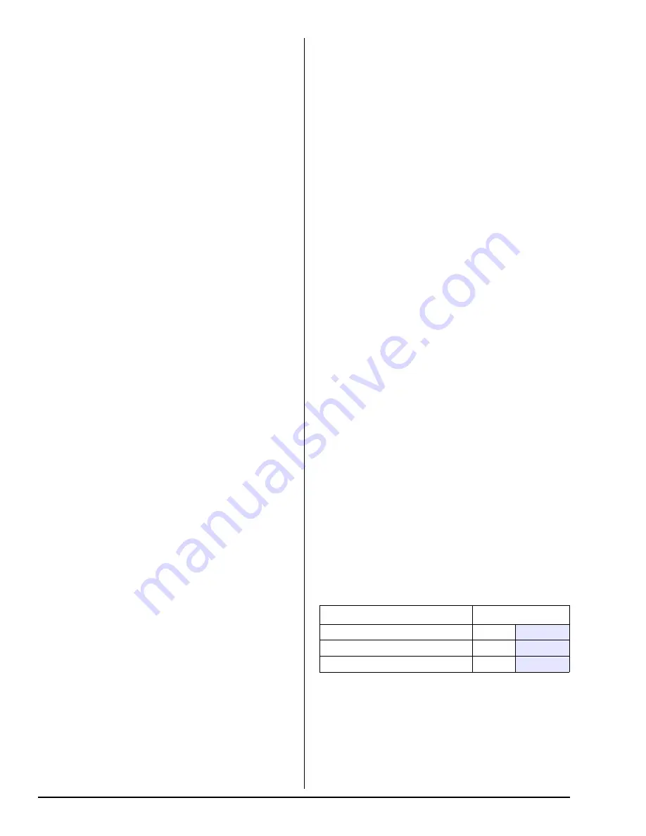
Air Pressure

 Normal

80 psi

5.51 bar

 Minimum Supply

70 psi

4.82 bar

 Maximum Supply

90 psi

6.21 bar

Check to ensure that the tumbler starts in the clockwise
direction.  Additionally, check the direction of the motorized
impellor to ensure that the motorized impellor rotates in the
clockwise direction as viewed from the front.  If it is, the
phasing is correct.  If the phasing is incorrect, reverse two
of the leads at L1, L2, or L3 of the power supply connections
made to the dryer.

IMPORTANT: Motorized impellor as viewed from the front
must turn in the clockwise direction, otherwise the dryer
efficiency will be drastically reduced and premature
component failure can result.

Heat Circuit Operational Test
Gas Models

When the dryer is first started (during initial start-up), the
burner has a tendency not to ignite on the first attempt.  This
is because the gas supply piping is filled with air, so it may
take a few minutes for this air to be purged from the lines.

The dryer is equipped with a DSI system, which has internal
diagnostics.  If ignition is not established after three attempts,
the heat circuit DSI module will LOCKOUT until it is manually
reset.  To reset the DSI system, open and close the main
door and restart the dryer (press the “START” key).

NOTE: During the purging period, check to be sure that
all gas shutoff valves are open.

Once ignition is established, a gas pressure test should be
taken at the gas valve pressure tap of each dryer to assure
that the water column pressure is correct and consistent.

NOTE: The water column pressure requirements
(measured at the gas valve pressure tap)…
Natural Gas ............. 3.5 in WC (8.7 mb)
L.P. Gas .................. 10.5 in WC (26.1 mb)

IMPORTANT: There is no regulator provided in an L.P.
dryer.  The water column pressure must be regulated at
the source (L.P. tank) or an external regulator must be
added to each dryer.

Steam Models

Check to ensure that the (standard) steam damper or
(optional) steam solenoid valve is functioning properly

The steam damper should not “slam” (open or closed) when
it reaches the end of (piston) travel.  Additionally, the steam
damper should not bind and/or stop during travel.  If either
of these conditions occur, the flow control must be adjusted.
Refer to the bottom illustration on the previous page for air
adjustment instructions.

Make a complete operational check of all safety-related
circuits (i.e., lint drawer switch and sail switch on gas
models).

NOTE: To check for proper sail switch operation, open the
main door and while holding main door switch plunger in,
start the dryer.  The dryer should start but the heat circuit
should not be activated (on).  If the heat (burner) does
activate, shut the dryer off and make the necessary
adjustments.

Reversing tumbler dryers should never be operated with less
than a 79 lb (35.83 kg) load (dry weight), since the load’s
weight affects tumbler coast time during a direction reversal
command.  It is important that the tumbler come to a
complete stop prior to starting in opposite direction.

Microprocessor Controller (Computer)

Dryer Models

Spin and stop times are not adjustable in the Automatic Mode
and have been preprogrammed into the microprocessor
controller (computer) for 150-seconds spin time in the
forward direction and 120-seconds in the reverse direction
with a 5-second dwell (stop) time.

Spin and stop times are adjustable in the Manual (timed)
Mode.

Tumbler Coating

The tumbler is treated with a protective coating.  We suggest
dampening old garments or cloth material with a solution of
water and nonflammable mild detergent and tumbling them
in the tumbler to remove this coating.

Each dryer should be operated through one complete cycle
to assure that no further adjustments are necessary and
that all components are functioning properly.

Make a complete operational check of all operating
controls…

Microprocessor controller (computer)

programs / selections…

Each computer has been preprogrammed by the factory with
the most commonly used parameter (program) selections.
If computer program changes are required, refer to the
computer programming manual, which was shipped with the
dryer.

Compressed Air Requirements _______

The dryer requires an external supply of compressed air
(2.50 cfh at 80 psi [0.07 cmh at 5.51 bar] for gas models
and 3.25 cfh at 80 psi [0.09 cmh at 5.51 bar] for steam
models).  For steam models, compressed air is necessary
for the standard air operated steam damper.  On both the
steam models as well as the gas models, compressed air is
necessary/required for blower air jet operation to clean lint
from the impellor/fan (squirrel cage).

Air Requirements

Microprocessor Controller (Computer) Dryers…

Shaded areas are stated in metric equivalents

Air Regulation

No air regulation or air filtration is provided with the dryer.
External regulation/filtration of 80 psi (5.51 bar) must be
provided.  It is suggested that a filter/regulator/gauge
arrangement be added to the compressed air line just before
the dryer connection.  This is necessary to ensure that correct
and clean air pressure is achieved.

Summary of Contents for D120

Page 1: ...e gaz depuis un voisin Suivez les instructions du fournisseur Si vous ne pouvez rejoindre le fournisseur de gaz appelez le service des incendies L installation et l entretien doivent être assurés par un installateur ou un service d entretien qualifié ou par le fournisseur de gaz WARNING For your safety the information in this manual must be followed to minimize the risk of fire or explosion and to...

Page 2: ...__________________________________________________ ___________________________________________________________________________________________________ Replacement parts can be obtained from your distributor or JLA When ordering replacement parts from JLA you can FAX your order to JLA at 01422 824390 or telephone your order directly to the JLA Parts Department at 01422 822282 Please specify the dry...

Page 3: ...i limit switch trips a service call is required to investigate the reason and resolve the issue FOR YOUR SAFETY Do not dry mop heads in the dryer Do not use dryer in the presence of dry cleaning fumes The dryers must not be installed or stored in an area where it will be exposed to water and or weather The wiring diagram for the dryer is located in the front electrical control box area Table of Co...

Page 4: ...tumbler may damage plastics or rubber and may be a fire hazard The possible presence of residual quantities of aggressive or decomposed chemicals in the load may produce damage to the machine and harmful fumes A program should be established for the inspection and cleaning of lint in the burner area exhaust ductwork and area around the back of the dryer The frequency of inspection and cleaning can...

Page 5: ..._______________ _______________________________________________________________________________________________________________________________ _______________________________________________________________________________________________________________________________ _______________________________________________________________________________________________________________________________ ...

Page 6: ...OXIMATE SHIPPING WEIGHT 1 430 lb 648 64 kg AIRFLOW 60 Hz 2 800 cfm 79 29 cmm 50 Hz 2 333 cfm 66 06 cmm EXHAUST CONNECTION DIAMETER 16 40 64 cm COMPRESSED AIR CONNECTION 1 4 Quick Connection COMPRESSED AIR VOLUME 2 50 cfh 0 07 cmh OVEN SIZE kW Btu hr kcal hr 72 245 729 61 923 VOLTAGE AVAILABLE 208 480v 3ø 3 4w 50 60 Hz APPROXIMATE NET WEIGHT 1 450 lb 657 71 kg APPROXIMATE SHIPPING WEIGHT 1 500 lb 6...

Page 7: ...hone 01422 822282 7 Mechanical Specifications _______________________________________________________ NOTE The manufacturer reserves the right to make changes in specifications at any time without notice or obligation ...

Page 8: ...outside as noted in this manual refer to Exhaust Requirements section The dryer must be located in an area where correct exhaust venting can be achieved as noted in this manual refer to Exhaust Requirements section IMPORTANT The dryer should be located where a minimum amount of exhaust ducting will be necessary The dryer must be installed with adequate clearance for air openings into the combustio...

Page 9: ...ms are located above the dryers a minimum of 18 inches 45 72 cm above the dryer console module is required Dryers may be positioned sidewall to sidewall however 1 or 2 inches 2 54 or 5 08 cm is suggested for ease of installation and maintenance Allowances must be made for the opening and closing of the control door and the lint door Fresh Air Supply Requirements ______ This appliance may only be i...

Page 10: ...haust Requirements _______________ General Exhaust Ductwork Information Exhaust ductwork should be designed and installed by a qualified professional Improperly sized ductwork will create excessive back pressure which results in slow drying increased use of energy overheating of the dryer and shut down of the burner by the airflow sail switches burner hi limits or tumbler hi heat thermostats The d...

Page 11: ...t be greater than 3 1 2 to 1 These figures must be increased in proportion if the main duct run to the last dryer to where it exhausts to the outdoors is unusually long over 20 feet 6 09 meters or has numerous elbows more than two in it In calculating ductwork size the cross sectional area of a square or rectangular duct must be increased twenty percent for each additional 20 feet 6 09 meters The ...

Page 12: ...ctwork can only be increased to an extent Maximum proportional ductwork runs cannot exceed 20 feet 6 09 meters more than the original limitations of 20 feet 6 09 meters with two elbows When the ductwork approaches the maximum limits as noted in this manual a professional HVAC firm should be consulted for proper venting information Exhaust back pressure measured by a manometer magnehelic in the exh...

Page 13: ...ION The ground connection may be to a proven earth ground at the location service panel NOTE A grounding connection terminal lug is provided in the dryer s electrical service relay box at the rear upper left hand corner of the dryer For added personal safety when possible it is suggested that a separate ground wire sized per local codes be connected from the ground connection of the dryer to a gro...

Page 14: ...s supply shutoff and an external gas supply shutoff must be provided Technical Data Gas Specifications Gas Connections Inlet connection 1 F B S P T Inlet supply size 1 1 4 N P T minimum Btu hr input 375 000 94 498 kcal hr Natural Gas Regulation is controlled by the dryer s gas valve s internal regulator Incoming supply pressure must be consistent between a minimum of 6 0 inches 14 92 mb and a maxi...

Page 15: ...89 47 kPa Installation Instructions To ensure an adequate supply of steam is provided be sure that the steam supply lines and steam return lines are sized and laid out as stipulated in this manual Inadequate steam supply lines and steam return lines or improper steam plumbing will result in poor performance and can cause component failure Clean dry steam must be provided to the dryer IMPORTANT Ste...

Page 16: ...ed with coil positioned directly above the valve body The supply line and the return line should be insulated This will save energy and provide for the safety of the operator and maintenance personnel Water pockets in the supply lines caused by low points will provide wet steam to the coil possibly causing steam coil damage All horizontal runs of steam supply piping should be pitched 1 4 inch 6 35...

Page 17: ...tric box covers have been replaced Check all service doors to assure that they are closed and secured in place Be sure the lint drawer is securely in place NOTE Lint drawer must be closed to activate the safety switch otherwise the dryer will not start Rotate the tumbler drum by hand to be sure it moves freely Check bolts nuts screws terminals and fittings for security STEAM MODELS check to ensure...

Page 18: ...witch on gas models NOTE To check for proper sail switch operation open the main door and while holding main door switch plunger in start the dryer The dryer should start but the heat circuit should not be activated on If the heat burner does activate shut the dryer off and make the necessary adjustments Reversing tumbler dryers should never be operated with less than a 79 lb 35 83 kg load dry wei...

Page 19: ...bustible The accumulation of lint can create a potential fire hazard Keep dryer area clear and free from combustible materials gasoline and other flammable vapors and liquids NOTE Remove power from the dryer before performing any maintenance in the dryer Suggested time intervals shown are for average usage which is considered six to eight operational running hours per day IMPORTANT The dryer produ...

Page 20: ... or continue through the drying cycle with no heat Manual reset hi limit must be reset manually This hi temperature condition may be caused due to a restricted exhaust poor airflow or improper burner operation The location of the burner hi limit is on the left side of the burner box looking at the burner from the back of the dryer WARNING Discontinue power to dryer before attempting to reset hi li...

Page 21: ...ignitor will shut off and the gas valve will be energized Ignition flame should now be established With the burner flame on remove the flame sensor wire from the S2 terminal of the HSI module The burner flame must shut off immediately CE Label 4 Heat Input For Gas Dryers This describes the heat input in British thermal units per hour Btu hr or kilowatts kW 5 Orifice Size For Gas Dryers Gives the n...

Page 22: ...hen the L E D is ON AUX _ This L E D will indicate the status of the S A F E system output If the request to turn on the S A F E system is made then the L E D is ON Input Output Board Input Description Red L E D FUSE _ This L E D will indicate the status of the F2 which fuses the 24 VAC supplied to the board LINT _ This L E D will indicate the status of the Lint Drawer If the drawer is closed then...

Page 23: ...haust temperature rise 25 F greater than set point this will be the trip point and the S A F E system routine will activate Once the S A F E system routine is activated water will be injected into the tumbler chamber Anytime water is being injected into the tumbler the tumbler drive will turn the load for 1 second every 15 seconds This process will continue for a minimum of 2 minutes After 2 minut...

Page 24: ...Part No 113375 16 12 01 15 ...

Reviews: