background image


User’s Manual


41 

  Once the password feature is used, you will be requested to type the password each time you enter BIOS 
setup. This will prevent unauthorized persons from changing your system configurations. 
Also,  the  feature  is  capable  of  requesting  users  to  enter  the  password  prior  to  system  boot  to  control 
unauthorized access to your computer. Users may enable the feature in. 
Security Option of Advanced BIOS Features. If Security Option is set to System, you 
will be requested to enter the password before system boot and when entering BIOS 
setup; if Security Option is set to Setup, you will be requested for password for entering 
BIOS setup. 
 

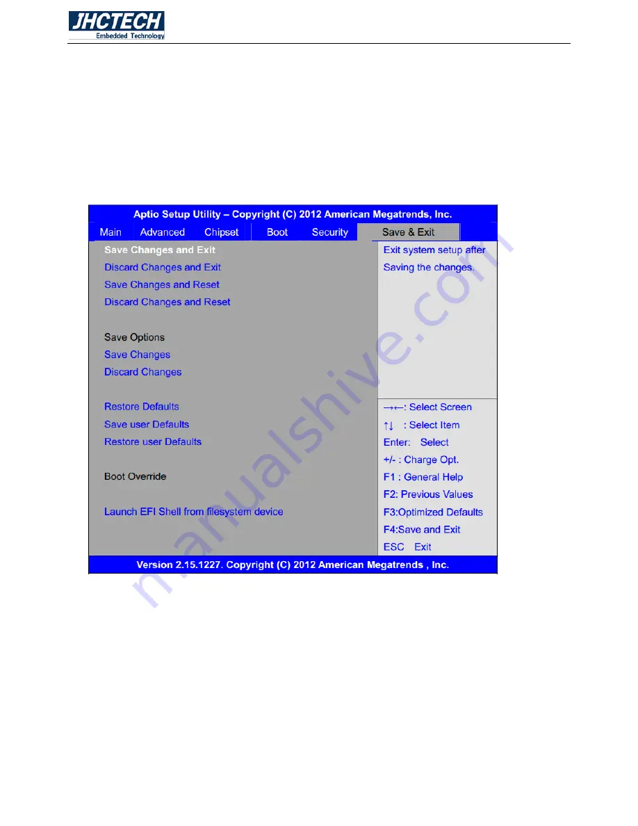
3.12 Save & Exit Menu 


                                                                        Figure 3.6 

Save Changes and Exit 
      Save & Exit Setup save Configuration and exit ? 
                                          [Yes] 
                                          [No] 
Discard Changes and Ext 
      Exit Without Saving Quit without saving? 
                                          [Yes] 
                                          [No] 
Save Changes and Reset 
      Save & reset Save Configuration and reset? 
                                          [Yes] 
                                          [No] 

Summary of Contents for FEBC-3158

Page 1: ...uminum Chassis Fanless disign 2 2nd 3rd Intel Core I3 I5 I7 CPU 3 Intel HM77 Chipset 4 2xDDR3 1333 SODIMM Max 8GB 5 2xMini PCIe PCIe USB signal mSATA 6 1xDVI I display and Audio 7 6xCOM 2xLAN 2xUSB3 0 4xUSB2 0 8 1x mSATA 1x2 5 3 5 HDD Bay 9 DC 12V Power Input 10 HDD Anti vibration design ...

Page 2: ...User s Manual 2 Version Note No Ver Note Date Writer 1 A1 0 first publish 20151106 Colin Cheng ...

Page 3: ...ntended to be accurate and reliable However Shenzhen JHC Technology Co Ltd assumes no responsibility for its use nor for any infringements of the rights of third parties which may result from its use Acknowledgements Award is a trademark of Award Software International Inc IBM PC AT PS 2 and VGA are trademarks of International Business Machines Corporation Intel and Pentium are trademarks of Intel...

Page 4: ...ent materials service time and freight Please consult your dealer for more details If you think you have a defective product follow these steps 1 Collect all the information about the problem encountered For example CPU speed JHC products used other hardware and software used etc Note anything abnormal and list any onscreen messages you get when the problem occurs 2 Call your dealer and describe t...

Page 5: ...nce when the equipment is operated in a commercial environment This equipment generates uses and can radiate radio frequency energy and if not installed and used in accordance with the instruction manual may cause harmful interference to radio communications Operation of this equipment in a residential area is likely to cause harmful interference in which case the user will be required to correct ...

Page 6: ...P3 COM6 Jumper Setting 9 2 4 I O indication 10 2 4 1 Ethernet Connector LAN 11 2 4 2 Power Input Connector DC IN 11 2 4 3 USB Connector 12 2 4 4 COM1 6 Connector 12 2 4 5 COM2 3 4 6 Connector 13 2 4 6 COM5 Connector 13 2 4 7 SATA_P1 SATA_P3 SATA Hard Disk Power out Connector 14 2 4 8 SATA_P2 SATA Hard Disk Power out Connector 14 2 4 9 SATA1 SATA2 14 2 4 10 SATA3 SATA4 14 2 4 11 Digital IO 14 2 5 I...

Page 7: ...set Setting 31 3 10 Boot Setting 错误 未定义书签 3 11 Security Settings 40 3 12 Save Exit Menu 41 Driver Installation 43 4 1 Follow the sequence below to install the drivers 44 4 2 Installation 44 System Resource 46 5 1 WDT Function 47 5 2 Digital IO Function 49 ...

Page 8: ...User s Manual 1 General Information CHAPTER 1 ...

Page 9: ...4 1x mSATA and 1x SATA3 HDD Bay 5 1x Mini PCIe with PCIex1 and USB signal Full size 6 2xGigabit Ethernet 7 1xDVI I display 8 2xUSB 3 0 4xUSB 2 0 9 5xRS232 1xRS422 485 10 1x Line out and 1x MIC 11 8 bit DIO 12 DC 12V power input 1 3 Specifications 1 3 1 General CPU Socket G2 2nd 3rd Intel Core I3 I5 I7 BIOS AMI 16M Flash ROM System Memory 1xDDR3 1333MHz Up to 8GB Watchdog Timer 255 level interval t...

Page 10: ...5 2430M 2 4GHz with 4GB DDR3 memory Power Adapter AC to DC 12V 5A 60 W Power Requirement Minimum power input DC 12V 3 8A 1 4 Environmental Specifications Operating temperature 20 70 SSD 10 50 HDD Relative humidity 95 60 C non condensing Storage temperature 40 85 C 40 185 F Vibration loading during operation With SSD mSATA 3 Grms IEC 60068 2 64 random 5 500 Hz 1 hr axis Shock during operation With ...

Page 11: ...User s Manual 4 FEBC 3158 S001 Dimensions Uint mm Figure 1 1 ...

Page 12: ...User s Manual 5 Hardware Installation CHAPTER 2 ...

Page 13: ...d in an aluminum plate chassis Your HDD and SDRAM are all readily accessible by removing the aluminum bottom cover Any maintenance or hardware upgrades can be easily completed after removing the bottom cover Warning Do not remove any mechanical parts until you have verified that no power is flowing within the Embedded Box Computer Power must be switched off and the power cord must be unplugged Mai...

Page 14: ...tal pins and a small metal clip often protected by a plastic cover that slides over the pins to connect them To close a jumper you connect the pins with the clip To open a jumper you remove the clip Sometimes a jumper will have three pins labeled 1 2 and 3 In this case you would connect either pins 1 and 2 or pins 2 and 3 Figure 2 3 The jumper settings are schematically depicted in this manual as ...

Page 15: ...bedded Box Computer has a number of jumpers inside the chassis that allows you to configure your system to suit your application The table below lists the functions of the various jumpers The table below shows the function of each of the board s jumpers Figure 2 5 Jumpers Jumper Name Description RTC1 SRTC1 CMOS RAM Clear Function Setting 2 Pin Block PS_ON Auto Power On Setting 2 Pin Block JP1 COM1...

Page 16: ...al defaults e After the above operations save changes and exit BIOS Setup RTC1 SRTC1 CMOS Open NORMAL Default Close 1 2 Clear CMOS 2 3 2 PS_ON 2 0mm Pitch 1X2 Pin Header ATX Power and Auto Power on jumper setting PS_ON Mode Close 1 2 Auto Power On Default Open ATX Power 2 3 3 JP1 COM1 Jumper Setting 2 0mm Pitch 2x3 Pin Header COM1 jumper setting pin 1 6 are used to select signal out of pin 9 of CO...

Page 17: ...User s Manual 10 2 4 I O indication Front view Rear view Figure 2 14 ...

Page 18: ...ts Figure 2 15 Ethernet Connector Table 2 1 RJ 45 Connector pin assignments Pin 10 100 1000BaseT Signal Name 1 TX 10 100 BI_DA GHz 2 TX 10 100 BI_DA GHz 3 RX 10 100 BI_DB GHz 4 BI_DC GHz 5 BI_DC GHz 6 RX 10 100 BI_DB GHz 7 BI_DD GHz 8 BI_DD GHz 2 4 2 Power Input Connector DC IN The FEBC 3158 comes with a 4 pole DIN jack that 12V external power input Please refer to Table 2 2 for their pin assignme...

Page 19: ...at con forms to the USB interface Many recent digital devices conform to this standard The USB interface supports Plug and Play which enables you to connect or disconnect a device whenever you want without turning off the computer Figure 2 17 USB connector Table 2 3 USB Connector Pin Signal name 1 VCC 2 USB_P0 3 USB_P0 4 GND The FEBC 3158 provides 2 USB3 0 ports by type A con nectors Please refer ...

Page 20: ... serial devices 1 2 3 4 5 6 7 8 9 Figure 2 19 COM1 3 Connector Table 2 5 COM1 3 Serial Port Pin Assignments Pin Signal Name 1 DCD 2 RxD 3 TxD 4 DTR 5 GND 6 DSR 7 RTS 8 CTS 9 JP1 JP3 Select Setting RI 5V 12V 2 4 5 COM2 3 4 5 Connector The FEBC 3158 provides COM2 3 4 5 are all D sub 9 pin connectors rear serial port standard RS232 DB9 Male serial port is provided to make a direct connection to seria...

Page 21: ...NC 2 4 7 SATA_P1 SATA_P3 SATA Hard Disk Power out Connector 2 5mm Pitch 1x2 Pin wafer Connector Two onboard 5V output connectors are reserved to provide power for SATA devices Table 2 8 SATA Hard Disk Power out Pin Assignments Pin Signal Name 1 DC 5V 2 GND Note Output current of the connector must not be above 1A 2 4 8 SATA_P2 SATA Hard Disk Power out Connector 2 5mm Pitch 1x4 Pin wafer Connector ...

Page 22: ... 2 SATA 6Gb s ports 2 4 10 SATA3 SATA4 SATA 7P SATA Connectors Two SATA connectors are provided High speed storage interface supporting up to 2 SATA 3Gb s ports Table 2 10 SATA Ports Color Position Function Color SATA1 SATA 3 0 Blue SATA2 SATA 3 0 Blue SATA3 SATA 2 0 Black SATA4 SATA 2 0 Black 2 4 11 Digital IO Figure 2 21 DIO Connector Table 2 11 Digital IO Port Pin Assignments Pin Signal Pin Sig...

Page 23: ...2 Screw the HDD SSD on the drive bay though 6 screws Step 3 Place the drive bay into the bottom cover Step 4 Screw 4 screws on the drive bay with the bottom cover Step 5 Use the SATA cable connect the SATA drive and the SATA power data connector of mother board Step 6 Close the HDD cover screw the 4 screws on the bottom cover Figure 2 23 ...

Page 24: ...User s Manual 17 Figure 2 24 Figure 2 25 ...

Page 25: ...User s Manual 18 Figure 2 26 2 5 2 Installing mSATA Flash Card mini PCIe SATA Step 1 Unscrew the 4 screws on the bottom cover and open the HDD cover Figure 2 27 ...

Page 26: ... mSATA Flash Card on this place as shown in the picture Figure 2 28 Step 3 Hold the Module with its notch aligned with the socket of the board and insert it at a 30 degree angle into the socket as shown in the picture Figure 2 29 ...

Page 27: ...User s Manual 20 Step 4 Screw one screws to the holder as shown in the picture Figure 2 30 Step 5 Close the HDD cover screw the 4 screws on the bottom cover Figure 2 31 ...

Page 28: ...User s Manual 21 BIOS Setup CHAPTER 3 ...

Page 29: ...annel for hardware and software to communicate it is the key factor for system stability and in ensuring that your system performance as its best 3 2 Entering Setup Power on the computer and by pressing Del immediately allows you to enter Setup If the message disappears before your respond and you still wish to enter Setup restart the system to try again by turning it OFF then ON or pressing the R...

Page 30: ... Option Page Setup Menu Press F1 to pop up a small help window that describes the appropriate keys to use and the possible selections for the highlighted item To exit the Help Window press Esc 3 6 Menu Bars There are six menu bars on top of BIOS screen Main To change system basic configuration Advanced To change system advanced configuration Chipset To change chipset configuration Security Passwor...

Page 31: ... time Please use Tab to switch between time elements the time format is Hour 0 to 23 Minute 0 to 59 Second 0 to 59 3 8 Advanced Setting Figure 3 2 PCI Subsystem Settings PCI Bus Driver Versio V2 05 02 PCI 64bit Resources Handling Above 4G Decoding Disabled Enabled PCI Common Settings ...

Page 32: ... Generation Disabled Enabled PCI Express Device Settings Relaxed Ordering Disabled Enabled Extended Tag Disabled Enabled No Snoop Enabled Disabled Maximum Payload Auto 128 Bytes 256 Bytes 512 Bytes 1024 Bytes 2048 Bytes 4096 Bytes Maximum Read Request Auto 128 Bytes 256 Bytes 512 Bytes 1024 Bytes 2048 Bytes 4096 Bytes PCI Express Link Settings ASPM Support Disabled Enabled WARNING Ebabling ASPM ma...

Page 33: ...nly CPU Stop RAM Lock Legacy Resources Disabled Enabled S3 Video Repost Disabled Enabled CPU Configuration Socket 0 CPU Information Intel R Core TM i7 2620M CPU 2 70GHz CPU Signature 206a7 Microcode Patch 28 Max CPU Speed 2700 MHz Min CPU Speed 800 Mhz Processor Cores 2 Intel HT Technology Supported Intel VT x Technology Supported Intel SMX Technology Supported 64 bit Supported Hype threading Enab...

Page 34: ...d IDE Legacy Native Mode Selection Native Lrgacy Serial ATA Port 0 Empty Software Preserve Unknown Serial ATA Port 1 Empty Software Preserve Unknown Serial ATA Port 2 Empty Software Preserve Unknown Serial ATA Port 3 Empty Software Preserve Unknown Serial ATA Port 4 Empty Software Preserve Unknown Serial ATA Port 5 Empty Software Preserve Unknown Thermal Configuration Platform Thermal Configuratio...

Page 35: ... Configuration PIntel R Anti Theft Technology Disabled Enabled Intel R Anti Theft Technology Rec 3 Enter Intel R AT Suspend Mode Disabled Enabled AMT Configuration Intel AMT Enabled Disabled BIOS Hotkey Pressed Disabled Enabled MEBx Selection Screen Disabled Enabled Hide Un Configure ME Confirmation Disabled Enabled MEBx Debug Message Output Disabled Enabled Un Configure ME Disabled Enabled Amt Wa...

Page 36: ...SB Support Enabled Disabled USB3 0 Support Enabled Disabled XHCI Hand off Disabled Enabled EHCI Hand off Disabled Enabled Port 60 64 Emulation Enabled Disabled USB hardware delays and time outs USB transfer time out 20 sec 10 sec 5 sec 1 sec Device reset time out 20 sec 10 sec 30 sec 40 sec Device power up delay Auto Manual Super IO Configuration PSuper IO Configuration Serial Port 1 Configuration...

Page 37: ...92 V 3 3V 3 424 V 1 5V 1 520 V AVCC 5 158 V Platform Misc Configuration Native PCIE Enable Disabled Enabled Intel R Smart Console Technology PISCT Configuration Disabled Enabled Serial Port Console Redirection Intel RC Drivers Version Detail CPU PPM Configuration CPU PPM Configuration EIST Enabled Disabled Turbo Mode Enabled Disabled CPU C3 Report Enabled Disabled CPU C6 report Enabled Disabled CP...

Page 38: ... power limit 0 ACPI T State Disabled 3 9 Chipset Setting Figure 3 3 System Agent SA Configuration System Agent SA Bridge Name Sandybridge System Agent RC Version 1 6 0 0 VT d Capability Supported VT d Enabled Disabled CHAP Device B0 D7 F0 Disabled Enabled Thermal Device BO D4 F0 Disabled Enabled ...

Page 39: ...8 IGFX Frequency 650 MHz Primary Display Auto IGFX PEG PCI Internal Graphics Auto Disabled Enabled GTT Size 2MB 1MB Aperture Size 256MB 128MB 512MB DVMT Pre allocated 64M 32M 96M 128M 160M 192M 224M 256M 288M 320M 352M 384M 416M 448M 480M 512M 1024M Dvmt Total Gfx Mem 256MB 128MB MAX GFX Low Power Mode Enabled Disabled ...

Page 40: ...1024 18bit 1ch 1280 X 1024 24bit 2ch 1366 X 768 18bit 1ch 1440 X 900 24bit 2ch 1600 X 900 24bit 2ch 1600 X 1200 24bit 2ch 1680 X 1050 24bit 2ch 1680 X 1050 24bit 2ch 1920 X 1080 24bit 2ch 2048 X 1536 24bit 2ch Panel Scaling Auto Off Force Scaling Backlight Control DC PWM Backlight Logic Positive Negaive Backlight Control Control Level Level 8 Level 0 Level 1 Level 2 Level 3 Level 4 Level 5 Level 6...

Page 41: ...ler Calibrate Auto Swing Control Full Gen3 Equalization Enabled Gen3 Eq Phase 2 Auto PEG Gen3 Root Port Preset Value for each Lane PEG Gen3 Endpoint Preset Value for each Lane PEG Gen3 Endpoint Hint Value for each Lane Gen3 Eq Preset Search Disabled PEG Link Disabled Disabled Fast PEG Init Enabled RxCEM Loop back Disabled PCIe Gen3 RxCTLEp Setting Memory Configuration Memory RC Version 1 2 2 0 Mem...

Page 42: ...v ID 04 C1 PCI Express Configuration PCI Express Clock Gating Enabled Disabled DMI Link ASPM Control Enabled Disabled DMI Link Extended Synch Control Disabled Enabled PCIe USB Glitch W A Disabled Enabled Subtractive Decode Disabled Enabled PCI Express Root Port 1 PCI Express Root Port 2 PCI Express Root Port 3 PCI Express Root Port 4 PCI Express Root Port 5 PCI Express Root Port 6 PCI Express Root...

Page 43: ...bled EHCT2 Enabled Disabled USB Ports Per Port Disable Control Disabled Enabled PCH Azalia Configuration Azalia Ato Disabled Enabled Azalia Docking Support Disabled Enabled Azalia PME Disabled Enabled Azalia Internal HDMI Codec Disabled Enabled BIOS Security Configuration SMI Lock Disabled Enabled BIOS Lock Disabled Enabled GPIO Lock Disabled Enabled BIOS Interface Lock Enabled Disabled RTC RAM Lo...

Page 44: ...Deepsx Display Logic Enabled Disabled CLKRUN Logic Enabled Disabled SB CRID Disabled Enabled High Precision Event Timer Configuration High Precision Timer Enabled Disabled SLP_S4 Assertion Width 4 5 Seconds 1 2 Seconds 2 3 Seconds 3 4 Seconds Disabled Restore AC Power Loss Power off Power on Last State ...

Page 45: ...gure 3 4 Setup Prompt Timeout 1 Bootup Numlock State On off Quiet Boot Disabled Enabled Fast Boot Disabled Enabled CSM16 Module Verison 07 69 Gatea20 Active Upon Request Always Option ROM Messages Force BIOS Keep Current IN19 Trap Response ...

Page 46: ...ot option Filter UEFI and Legacy Legacy only UEFI only Launch PXE OpROM policy Do not launch UEFI only Legacy only Launch Storage OpROM policy Legacy only UEFI only Do not launch Launch Video OpROM policy Legacy only UEFI only Do not launch Other PCI device ROM priority UEFI only Do not launch Legacy only ...

Page 47: ...usly typed CMOS passwords You will be requested to confirm the password abandon password entry operation A confirmation message will be shown on the screen as to whether the password will be disabled You will have direct access to BIOS setup without typing any password after system reboot once the password is disabled ...

Page 48: ...er Users may enable the feature in Security Option of Advanced BIOS Features If Security Option is set to System you will be requested to enter the password before system boot and when entering BIOS setup if Security Option is set to Setup you will be requested for password for entering BIOS setup 3 12 Save Exit Menu Figure 3 6 Save Changes and Exit Save Exit Setup save Configuration and exit Yes ...

Page 49: ...No Discard Changes Load Previous Values Load Previous Values Yes No Restore Defaults Load Optimized Defaults Load optimized Defaults Yes No Save user Defaults Save Values as User Defaults Save configuration Yes No Restore user Defaults Restore User Defaults Restore User Defaults Yes No Launch EFI Shell from filesystem device WARNING Not Found ok ...

Page 50: ...User s Manual 43 Driver Installation CHAPTER 4 ...

Page 51: ...n the infinst_autol exe 2 Follow the instructions that the window shows 3 The system will help you install the driver automatically Step 2 Intel HD Graphics Drivers 1 Click on the Step 2 Intel Graphics Media Accelerator Driver Production Version folder and select the OS folder your system is 2 Double click on the Setup exe file located in each OS folder 3 Follow the instructions that the window sh...

Page 52: ...p 7 Install Intel Rapid Storage Technology in the system 2 Double click on Setup exe file located in each OS folder 3 Follow the instructions that the window shows 4 The system will help you install the driver automatically Step 8 Install Intel Rapid Start Technology 1 Click on the Step 8 Install Intel Rapid Start Technology in the system 2 Double click on Setup exe file located in each OS folder ...

Page 53: ...User s Manual 46 SYSTEM RESOURCE CHAPTER 5 ...

Page 54: ...l IpMyin Myin IpMyout Myout hDll LoadLibrary _T inpout32 dll if hDll NULL Myin IpMyin GetProcAddress hDll Inp32 Myout IpMyout GetProcAddress hDll Out32 if Myin NULL Myout 0x4e 0x87 Myout 0x4e 0x87 unlock Myout 0x4e 0x2b Myout 0x4f 0xc0 select logical device Myout 0x4e 0x7 Myout 0x4f 0x8 select logical device Myout 0x4e 0x30 Myout 0x4f 0x01 Set Watch Dog Timer Activate Myout 0x4e 0xf5 Myout 0x4f 0x...

Page 55: ...er s Manual 48 Myout 0x4e 0xf6 Myout 0x4f time set counts Myout 0x4e 0xaa lock FreeLibrary hDll 释放此 DLL void disable_watchdog set_watchdog 0 int _tmain int argc _TCHAR argv set_watchdog 5 getchar return 0 ...

Page 56: ...class CAboutDlg public CDialog public CAboutDlg Dialog Data AFX_DATA CAboutDlg enum IDD IDD_ABOUTBOX AFX_DATA ClassWizard generated virtual function overrides AFX_VIRTUAL CAboutDlg protected virtual void DoDataExchange CDataExchange pDX DDX DDV support AFX_VIRTUAL Implementation protected AFX_MSG CAboutDlg AFX_MSG DECLARE_MESSAGE_MAP CAboutDlg CAboutDlg CDialog CAboutDlg IDD AFX_DATA_INIT CAboutDl...

Page 57: ...adIcon IDR_MAINFRAME void CL706_GPIO_TESTDlg DoDataExchange CDataExchange pDX CDialog DoDataExchange pDX AFX_DATA_MAP CL706_GPIO_TESTDlg NOTE the ClassWizard will add DDX and DDV calls here DDX_Control pDX IDC_BTN_LED1 m_ButtonLED1 DDX_Control pDX IDC_BTN_LED2 m_ButtonLED2 DDX_Control pDX IDC_BTN_LED3 m_ButtonLED3 DDX_Control pDX IDC_BTN_LED4 m_ButtonLED4 DDX_Control pDX IDC_BTN_LED5 m_ButtonLED5 ...

Page 58: ...he framework does this automatically when the application s main window is not a dialog SetIcon m_hIcon TRUE Set big icon SetIcon m_hIcon FALSE Set small icon TODO Add extra initialization here LED s CWnd pWndLedBtn1 CWnd GetDlgItem IDC_BTN_LED1 m_ButtonLED1 SetLED pWndLedBtn1 ID_LED_GREEN ID_SHAPE_ROUND 500 m_ButtonLED1 SwitchOn m_ButtonLED1 LedOff CWnd pWndLedBtn2 CWnd GetDlgItem IDC_BTN_LED2 m_...

Page 59: ... m_ButtonLED7 SetLED pWndLedBtn7 ID_LED_GREEN ID_SHAPE_ROUND 500 m_ButtonLED7 SwitchOn m_ButtonLED7 LedOff CWnd pWndLedBtn8 CWnd GetDlgItem IDC_BTN_LED8 m_ButtonLED8 SetLED pWndLedBtn8 ID_LED_GREEN ID_SHAPE_ROUND 500 m_ButtonLED8 SwitchOn m_ButtonLED8 LedOff InitializeWinIo SetTimer 1 200 0 return TRUE return TRUE unless you set the focus to a control void CL706_GPIO_TESTDlg OnSysCommand UINT nID ...

Page 60: ...hIcon else CDialog OnPaint The system calls this to obtain the cursor to display while the user drags the minimized window HCURSOR CL706_GPIO_TESTDlg OnQueryDragIcon return HCURSOR m_hIcon BOOL CL706_GPIO_TESTDlg DestroyWindow TODO Add your specialized code here and or call the base class ShutdownWinIo KillTimer 1 return CDialog DestroyWindow void CL706_GPIO_TESTDlg Gpio2_Out_detect set GPIO is en...

Page 61: ...utput void CL706_GPIO_TESTDlg OnTimer UINT nIDEvent if CButton GetDlgItem IDC_CHECK_INOROUT GetCheck Gpio2_In_detect Gpio6_In_detect else m_ButtonLED1 LedOff m_ButtonLED2 LedOff m_ButtonLED3 LedOff m_ButtonLED4 LedOff m_ButtonLED5 LedOff m_ButtonLED6 LedOff m_ButtonLED7 LedOff m_ButtonLED8 LedOff Gpio2_Out_detect Gpio6_Out_detect CDialog OnTimer nIDEvent void CL706_GPIO_TESTDlg Gpio6_Out_detect un...

Page 62: ... 0x549 GPIO6 1 GPIO75 void CL706_GPIO_TESTDlg Gpio2_In_detect DWORD dwPortVal 0 set GPIO is enabled GPIO68 69 70 71 27 57 58 75 SetPortVal 0x540 0xF0 1 GPIO68 69 70 71 SetPortVal 0x541 0x08 1 GPIO75 SetPortVal 0x503 0x39 1 GPIO27 SetPortVal 0x533 0x16 1 GPIO57 58 set port2 is input SetPortVal 0x544 0xF0 1 GPIO68 69 70 71 SetPortVal 0x545 0x08 1 GPIO75 SetPortVal 0x507 0xAE 1 GPIO27 SetPortVal 0x53...

Page 63: ...1 LedOn else m_ButtonLED1 LedOff void CL706_GPIO_TESTDlg Gpio6_In_detect DWORD dwPortVal 0 GetPortVal 0x549 dwPortVal 1 GPIO75 if dwPortVal 3 0x01 m_ButtonLED8 LedOn else m_ButtonLED8 LedOff GetPortVal 0x53B dwPortVal 1 GPIO58 if dwPortVal 2 0x01 m_ButtonLED7 LedOn else m_ButtonLED7 LedOff GetPortVal 0x53B dwPortVal 1 GPIO57 if dwPortVal 1 0x01 m_ButtonLED6 LedOn else m_ButtonLED6 LedOff GetPortVa...

Page 64: ...User s Manual 57 m_ButtonLED5 LedOff ...

Reviews: