background image


JG special products GmbH                                                                                                      

Seite | 33


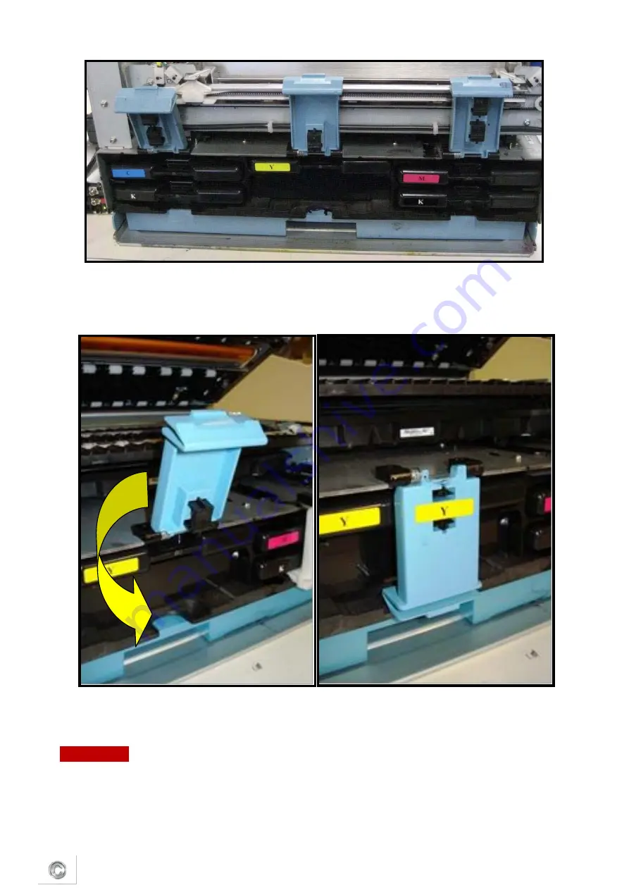
   Re-fasten each ink tank latch to ensure it moves properly and engages fully. If not, 

escalate to a technician for replacement. 


Cutter inspection and cleaning 


WARNING! 


To avoid personal injury, power off the printer before performing this task! 

  Fold a damp lint-free cloth and insert it into the groove beneath the cutter 

Summary of Contents for SPEEDSTAR 3000

Page 1: ...April 2012 JG special products GmbH Maintenance Tasks SPEEDSTAR 3000 ...

Page 2: ...ates 3 3 Removing CIS sensor 5 3 1 Removing CIS guide plates 7 4 Select cleaning programms 7 4 1 Cleaning commands 7 5 Removing glued labels 11 6 Standard maintenance 11 7 Daily maintenance tasks 13 8 Bi weekly maintenance tasks 16 9 Monthly maintenance tastks 19 10 Annual maintenance tasks 26 ...

Page 3: ...ur organization Copies of this document any portion of this document or attachments may not be transmitted or disclosed to any third party without the prior written permission of JG special products Gmbh 2012 JG special products GmbH All content is the confidential property of or licensed to JG special products GmbH JG special products GmbH we or us and is protected under German and Foreign copyri...

Page 4: ...oose yourself the cleaner For cleaning the print head and the CIS sensor a microfibre cloth is most useful You can also use other cloths but with a fine fuzz free texture For cleaning the paper sensor cotton sticks are most appropriate The cleaning should be carried out only with distilled water and no other detergents or liquids 2 Removing guide plates First remove the two screws of the guide pla...

Page 5: ...JG special products GmbH Seite 4 At this moment the two screws do not have to be removed You can now remove the guide plates by taking it out diagonally upwards Release ...

Page 6: ...s of glue are removed 3 Removing CIS sensor The CIS sensor is a very sensitive component and should therefore be handled carefully For this reason you should not use any tools in order to protect the sensor Lift the sensor out of the guide plates Please watch the connecting cables of the sensor They are not to be bended or squashed ...

Page 7: ... the connecting cables of the CIS sensor Do not rip or tear Afterwards you can clean the bottom side of the sensor The cleaning is to be carried out only with distilled water and a fine microfiber cloth otherwise the protective glass can be scratched ...

Page 8: ...tubes are not to be squashed or cutted Afterwards remove carefully backwards the Plastic frame from the printer The Plastic frame is to be cleaned with the cloth and the label remover until there are no more labels and adhesive rests 4 Select cleaning programs By wiping the print head the colours in the print head are mixed Therefore you have to start manually the cleaning procedure of the printer...

Page 9: ...JG special products GmbH Seite 8 In the main picture use the button Maintenance Click on the field Light clean 1 2 ...

Page 10: ...ead ink is being used and the print head is being worn Therefore you should first start with the weakest cleaning command as the individual functions are to be distinguished from each other in application After confirming the buttons a message with the needed time appears at all commands This can be carried out with YES for processing or NO for cancelling 3 ...

Page 11: ...use when light cleaning was ineffective Heavy Clean 3 Carries out a strong cleaning of the print head For use with strongly blazed colours wrong colours or strong stripes Prime Print Head Level 1 3 4 If there is no improvement with the blazed colours after the cleaning action the print head can be rinsed with ink This is also applied to empty tubes Basically you should start first with the lowest ...

Page 12: ...ses configurations may require more frequent maintenance NOTE Repair and replacement tasks are referred to qualified technicians For some maintenance tasks it is better to remove the engine from the printer Use the table below to determine which maintenance task inspection cleaning lubrication or replacement etc to perform at a given time period or usage interval The following tasks are to be perf...

Page 13: ...red low voltage the current is sufficient enough to cause injuries Cleaning table GOODYEAR Cleaning Bi weekly Monthly As Needed Morning Evening Night Printhead manual wipe xxx xx x x x x Sensors xxx x x x Wiper xxx x x Waste Ink absorber x x x Ink tubing x Lift motor gear x x x Moving parts motor test x x x Inktank latches x Cutter x x x x Service station x x x x Guide plates x x x x ...

Page 14: ...finds paper debris on a star wheel check to see whether or not it is aligned with the edge of the media If so you may need to adjust the paper guide and margin so that the star wheel no longer rubs the edge of the paper Perform this procedure with the printer powered on so the platen is raised Pinch the clamshell latches to release as shown on the pictures Open the clamshell and allow the upper po...

Page 15: ...free cloth to remove ink overspray aerosol and debris NOTE Do not wipe the star wheels as they may release and fall out Do not clean the printhead nozzle plate at this time it will be cleaned during another task Use a clean dry lint free cloth dry the inside of the unit Avoid the grit rollers since they can snag on the cloth and create debris Platen Gritrollers Housing ...

Page 16: ...JG special products GmbH Seite 15 Fold the cloth between wipes to ensure a clean uncontaminated surface is used each time Star wheels Pinch rollers ...

Page 17: ...mshell 8 5 Bi Weekly maintenance tasks Aerosol and debris removal Paper path optical sensor cleaning Wiper inspection Aerosol and debris removal see at daily maintenance tasks Optical sensor cleaning Clean the four optical sensors in the paper path every two weeks Pinch the clamshell latch to release and open the clamshell ...

Page 18: ...JG special products GmbH Seite 17 ...

Page 19: ...tilled water Place the damp swab on each sensor and twist back and forth to clean the surface Use a new moist swab on each sensor Repeat cleaning and drying process for all four sensors Wiper Inspection Pinch the clamshell latches to release and open the clamshell ...

Page 20: ...divots etc or delamination peeling of the wiper surface at the seam If irregularities are seen escalate to a technician for replacement Use tweezers to remove any large clumps of debris 8 6 Monthly maintenance tasks Aerosol and debris removal Paper path optical sensor cleaning Wiper inspection Waste ink absorber inpection Ink tubing inspection Lift motor gear inspection Paper path grit roller insp...

Page 21: ...he front of the unit and slide the tray out Even the absorber is completely darkened with waste ink with no white showing it may still be able to hold additional ink due to evaporation The capacity of the waste ink absorber is 1 6 L Visually inspect the waste ink absorber and tray to see if there is ink leaking out of the tray If yes replace the absorber with a new one Slide the waste ink tray bac...

Page 22: ...y month Fluidic coupling aka Revolver Caps Buffer box Pinch valve Peristaltic ink pump Refer to the following pictures to identify the specific hardwares Remove any housing or covers positioned around the ink tubing NOTE The clamshell should be closed during this procedure Tubing into fluidic couplings Peristaltic pump Pinch valve and vents x5 ...

Page 23: ... found escalate to a technician for troubleshooting Follow the exposed length of each tube and visually inspect each ink tube for kinks or pinches in the tubing Undo the irregularity to allow ink to flow freely Escalate to a technician if leaks result Re install the fluidic coupling covers Re install any housing removed to access this area Pinch valve and vents x5 Pump motor Buffer Box Ink Tubing ...

Page 24: ... inspected every month Inspect the lift motor gear for general wear worn teeth debris etc Remove any debris found If excessive wear is observed escalate to a technician for repair Use a lint free wipe damped with DI water to very gently clean exposed encoders Gently rotate the encoder after each wipe to ensure cleaning of the entire surface ...

Page 25: ...E On some printer there is a cover on the lift motor encoder that protects it from aerosol and debris No cleaning is required on these units Paper path grit roller inspection The three paper path grit rollers must be inspected every month ...

Page 26: ...ng steps to remove it Lightly moisten a toothbrush with a small amount of DI water Gently scrub the grit rollers to remove any ink or paper dust Manually rotate the rollers to ensure that they are completely clean Use a shop towel to dab the rollers and remove any excess moisture Do not rub the towel back and forth or fibers will be left on the grit rollers Grit rollers ...

Page 27: ...tion Aerosol and debris removal Paper path optical sensor cleaning Wiper cleaning Waste ink absorber inspection Ink tubing inspection Lift motor gear inspection Paper path grit roller inspection see at monthly maintenance tasks Moving parts motor test Activate the media path cutter pump pinch valves and maintenance module and listen for any noises not present when the printer was new Inspect the m...

Page 28: ...d for easy access Prepare a large absorbent towel to catch any ink which might leak from the maintenance module or the wick to the waste ink reservoir Make sure to fold the towel over 2 or 3 times so that it can absorb lots of ink Be prepared to cover the bottom of the maintenance module with the towel as you pull it out Manually rotate the maintenance module positioning gear until the module dise...

Page 29: ...nt free cloth is soiled use a new cloth Inspect both wicks printing platen and cap for warping plugged up sections or to see if it is falling out If fouled escalate to a technician for replacement with new wick s Inspect the cap for ink contamination and cracking or permanent deformation of the cap If permanently damaged escalate to a technician for replacement ...

Page 30: ...ule during the annual cleaning Use a vacuum cleaner for the interior of the unit if necessary Wiper cleaning Wiper cleaning usually means that the operator has to change the microfiber roller as it comes to the end of its lifetime The operator can easily recognize this stage First of all the shape of the roller turns from rounded to ellipse Secondly this change within the shape will cause signific...

Page 31: ...a year Disconnect the wiper motor connector PCB from the mounting clip Disconnect the wiper PCB from the ribbon cable as shown in the figure below Route the ribbon cable through the housing to free the wiper as shown on the next pictures Flip up the retention tab at each end of the wiper assembly to free the microfiber roller ...

Page 32: ... the transfer roller TR for unusual ink accumulation The transfer roller is stainless steel Ink may accumulate in scratches on the roller Wash the roller with damp lint free cloth if necessary Re assemble the wiper module In Liberty navigate to OneTouch Maintenance and press Home Service Station button to re install the MM into the print engine Retention tab ...

Page 33: ...n Release the three ink tank latches Carefully slide all five ink tanks one at a time out of the unit Verify that the Liberty reflects the tank removal Align each ink tank with the rails on the printer and insert Repeat until all five ink tanks are re installed ...

Page 34: ... it moves properly and engages fully If not escalate to a technician for replacement Cutter inspection and cleaning WARNING To avoid personal injury power off the printer before performing this task Fold a damp lint free cloth and insert it into the groove beneath the cutter ...

Page 35: ...nually wiped after the following occurrences after paper jams before re installing a used printhead cartridge into the print engine if print quality is showing signs of contamination if automated maintenance algorithms prove ineffective for nozzle recovery There are two methods for cleaning the print head cartridge one which is installed and one which is removed from the unit Both methods are list...

Page 36: ...g steps to ensure proper printhead cleaning without removing it Pinch the clamshell latches to release Open the clamshell and allow the upper portion to rest on the hard stops Locate the printhead nozzle strip Dampen a lint free cloth with distilled water ...

Page 37: ...d clean the nozzle plate again to remove remaining debris Close the clamshell Printhead cartridge cleaning remove cartridge Preparation Lightly dampen a lint free cloth with DI water Set the wipe on a clean surface Lightly moisten the cloth strip in a PH shipping cap with a small amount of DI water and set aside ...

Page 38: ...ect a USB keyboard to the printer then go to Start Run on the embedded PC and run CMD Type in the following command usbcmd c ph_release This command will de prime the system During de priming the printhead latch will release Listen for the latch to click and observe that it is popped up when release is successful ...

Page 39: ...JG special products GmbH Seite 38 Open the latch Tilt the printhead cartridge towards the rear of the unit until it clicks Don t open manually ...

Page 40: ...e 39 Slide the printhead cartridge out of the print engine Gently wipe the printhead from one end to the other with a lint free cloth moistened with DI water and then cap the printhead to keep it moist while performing other tasks ...

Page 41: ... Locate the PPCA contacts Use a new lint free cloth dampened with DI water to gently wipe up and down to clean the PPCA contacts CAUTION Use only a very gentle up and down motion never side to side because the contact pins are very easy to bend which can damage the printhead and the printhead circuit board PPCA contacts ...

Page 42: ...JG special products GmbH Seite 41 Locate the fluidic couplings Fluid couplings ...

Page 43: ... foam swab with DI water Place the foam swab in one of the ink channels on the fluidic coupling and rotate to clean Use a new moist foam swab and repeat the process for each ink channel on both fluidic couplings until all 10 openings are cleaned ...

Page 44: ...al products GmbH Seite 43 Remove the cap from the printhead Wipe from one end to the other with the damp lint free cloth Align the PH cartridge with the pin on the PPCA board and slide it into the print Engine ...

Page 45: ...ouplings will advance and seal to the printhead cartridge Close the printhead latch When the printhead latch is closed the printer will prime clean and cap the printhead automatically This operation will generally take a minute or two and will be apparent from sounds emanating from the print engine When the system is primed print a test printjob from Liberty to make sure the cleaning process was r...

Page 46: ... the tray out Use a gloved hand to pull the waste ink absorber out of the waste ink tray and dispose of it according to local regulations Align a new waste ink absorber with the shape of the waste ink tray and push into place until evenly seated and flush with the tray top edge Slide the waste ink tray back into the frame until it clicks ...

Reviews: