


15
render and tile
to inner edge
max thickness
render and tile
one rubber
gasket to front
and back of liner
clamping
frame
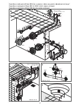
Installation Suggestion
4
1
2
suction
housing
3
20-35
(opt.
25)
60
24 max
30
45°
100
100
22,5°
15
17
8x
4
5
°-
3
6
0
22,5°
22,5°
26
M 6
60
30
20-35
(opt.
25)
M 5
10-35
Ø 0,7
8,6
6
x6
0°
= 360
10,2
24 max
5
suction pipe
Ø
20
100
24
60
24
optimal 25
20-35
24
10,2
Ø 17
protection tube
In case of a concrete wall
thickness of more than 24
cm, unscrew the protection
pipe and use the enclosed
protection tube.
use clamping frame for
cutting and drilling
poll wall
sunk screw
concrete
dimensions in cm
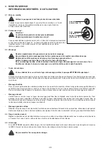
pool wall
water level
nozzle housing
clamping frame
screw 6 x 30
gasket
suction
housing
gasket
Pneumatics switch
housing
Shuttering
Protective sleeve
for pneumatic tube
Wall thickness
24 -100 cm
Water level
nozzle
housing
Sticker
„top“
stopper 2“
Shuttering
screw
If required
M 6x35
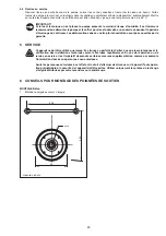
Shuttering
dimensions in cm
clamping frame
screw M 6
stopper 2“
water level
pool wall
water level
clamping frame
screw 6 x 30
gasket
dimensions in cm
drilling
water level
screw M 5
countersunk screw M5
Install the wall fitting of the second nozzle (MIRO2)
by keeping a lateral distance of 30 cm.
Assemble the wall
fitting of the third
nozzle (MIRO3)
centrically and 30 cm
towards below.
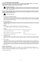
intake screen
intake screen


