JETStream UWE MIRO 1 Installation And Operating Instructions Manual Download Page 13

13

1

SAFETY INSTRUCTIONS

1.1 Before Setting into Operation

Before installation and setting into operation, the Safety Instructions and the Operating Instructions must be
carefully read and observed. You must definitely comply with the requirements of the uwe company and of the
standards authorities.

1.2 Setting the Unit into Operation for the First Time

Before the unit is set into operation, the local safety regulations and the Safety Instructions must always be complied with.

1.3 Sources of Danger

Warning!

The JETSTREAM system forces up to 700 litres of water per minute into the pool through the nozzle. If all of this enormous
force is used for massage, it can cause injuries to muscles and to connective tissue, as well as internal injuries. Because
of the reduced electrical resistance of the human body in swimming pools and the resulting increased probability of the
occurrence of dangerous currents in the body, increased safety requirements are imposed on the electrical installation.

Therefore, you must definitely observe the following Safety Instructions:

The JETSTREAM has substantial power. Before massage, you must definitely reduce the pressure.
Do not utilize full thrust against soft parts of the body.
Switch off pump before adjusting angle of nozzle.
For large-area massage, reduce the strength to half  thrust.
In order to attach and detach the massage fitting switch off the pump.
To massage a single part of the body, grip the massage hose firmly. When using the hose keep a distance
to those parts of the body that require massaging.
Do not approch the suction filter with long hair unless tied back.
Before putting the massage hose on or taking it off, switch off the pump.
For point massage, hold the nozzle of the massage hose firmly in your hand under water. Guide the nozzle
of the massage hose over the required places but at some distance from them.
Do not dive to the intake screen (if there is one) with long, unrestrained hair.

For requirements regarding the appropriate electrical installation, please see „Information for the Electrician“, as per part
7. Parts of the equipment that contain electrically live parts must be inaccessible to persons using the pool. Units and unit
parts containing electrical components must be installed or fixed in such a way that they cannot fall into the water. Units
of enclosure class I must be permanently connected to permanently laid cables.

1.4 Proper Operation

All units are intended soleley for operation in covered swimming pools and in open-air swimming pools with a water
temperature up to 35°C. The units are suitable for installing and operating in installations and rooms in areas 1 and 2 as
per EN-60335-2-41.

The pump is normally installed in the walkway behind the pool wall, but it must be ensured that the
environment is dry and that the motor is protected by a suitably sized floor drain to prevent flooding.

The control panel should be installed either in a dry walkway or in an adjacent room, if possible higher than the water
level. Any kind of use other than the intended use is improper. The manufacturer will not accept liability for any damage
or injury resulting from improper operation; the user alone must bear this risk. Proper operation also includes compliance
with the operating, maintenance and repair conditions specified by the manufacturer. Maintenance work, repair work and
suchlike may only be performed by authorised persons. The units may only be used by persons who are familiar with
them and who have been informed about the dangers. The relevant regulations for the prevention of accidents and the
other generally recognised rules relating to safety and to occupational medicine must be complied with. If unauthorised
modifications are made on the units, the manufacturer will not accept liability for any resulting damage or injury.

1.5 Product Liability

The user’s attention is expressly drawn to the fact that the unit may only be operated in the proper manner. If it is operated
in an improper manner, the user must bear sole responsibility. In such cases, therefore, the manufacturer cannot accept
any liability.

1.6 Procedure in an Emergency

Leave the water immediately, switch off the electrical supply to the unit by operating the main power switch or circuit-
breaker, and secure the unit to prevent it from being switched on again without authorisation.

1.7 Explanation of the Danger Symbols

Warning!
In these Operating Instructions, we have used this symbol to mark all texts which relate to your safety.
Please pass all safety instructions on to other users too.

In these Operating Instructions, we have used this symbol to mark all texts containing instructions that
are necessary for functional reasons. Please be sure to obey these instructions in order to avoid damage
to the unit.

Summary of Contents for UWE MIRO 1

Page 1: ...1 Montage und Bedienungsanleitung GB INSTALLATION AND OPERATING INSTRUCTIONS F INSTRUCTIONS DE MONTAGE ET MODE D EMPLOI MIRO 1 2 3...

Page 2: ...2 D Inhaltsverzeichnis MONTAGE UND BEDIENUNGSANLEITUNG Seite 3 11 GB Table of Contents INSTALLATION AND OPERATING INSTRUCTIONS page 12 21 F Contenu INSTRUCTIONS DE MONTAGE ET MODE D EMPLOI page 22 31...

Page 3: ...1 3 Gefahrenquellen Warnung Die JetStream Anlage spritzt durch die Strahld sen bis zu 780 Liter Wasser pro Minute in das Becken ein Wird diese enorme Kraft voll zur Massage eingesetzt kann dies zu Ve...

Page 4: ...llen die Ihre Sicherheit betreffen mit diesem Zeichen versehen Geben Sie alle Sicherheitsanweisungen auch an andere Benutzer weiter In dieser Bedienungsanleitung haben wir alle Stellen die funktionsno...

Page 5: ...and D senmantelgeh use f r D se Saugrohr D sen mantelgeh use Einlaufseiher Klemmrahmen Dichtung Senkschraube M6x30 Wasserspiegel Becken wand Klemmrahmen Dichtung Senkschraube Wasserspiegel Schutzschla...

Page 6: ...Senkbohrungen im Schaltergeh use decken Drehen Sie die Senkschrauben 1 ein Stecken Sie den im Beckenumgang befindlichen Schaltschlauch nachdem Sie ihn auf die erforderliche L nge gebracht haben auf d...

Page 7: ...em Wasserspiegels montieren 6 7 Ma e in cm MIRO 1 Einbauvorschl ge 8 9 11 10 19 20 23 1 2 3 4 5 6 7 12 13 14 15 16 17 22 21 18 24 Steuerkasten und Ventile ca 5 10 cm ber dem Wasserspiegels montieren 8...

Page 8: ...assage F r die gezielte Massage von bestimmten K rper und Muskelpartien verwenden Sie den Massageschlauch mit der kleinen D se Dabei halten Sie die Schlauchd se unter Wasser fest in der Hand und f hre...

Page 9: ...einwandfreiem Zustand betreiben Auf regelm igeWartung und berpr fung der technischen Einrichtungen achten Bei Reparatur bzw Wiederinbetriebnahmet tigkeiten sind zus tzli che Ma nahmen wie Absperrung...

Page 10: ...der 16 A K Sicherungsautomaten Leitungsl nge bzw Spannungsabfall beachten Bei 230 V Schmelzsicherungen 16 A tr ge oder 16 A K Sicherungsautomaten Leitungsl nge bzw Spannungsabfall beachten 4 Leistungs...

Page 11: ...N PE PE M bauseits Steuerkasten Pumpen aggregat 3x2 5 mm Die bauseitige Installation ist gem den g ltigen Bestimmungen wie z B DIN VDE TAB VBG UVV auszuf hren RD RD BN BU L1 N PE PE PE L1 N PE K1 F1 F...

Page 12: ...me you and or your personnel should definitely receive instructions from the specialist consultant If contrary to expectations techni cal defects occur in your unit please contact the customer service...

Page 13: ...not fall into the water Units of enclosure class I must be permanently connected to permanently laid cables 1 4 Proper Operation All units are intended soleley for operation in covered swimming pools...

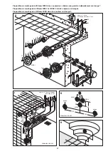
Page 14: ...ssembly of the unit MIRO 2 install the second MIRO wall fitting by keeping a lateral distance of 30 cm MIRO 3 has to be assembled centrically 30 cm in below direction see picture 4 For assembly of MIR...

Page 15: ...drilling poll wall sunk screw concrete dimensions in cm pool wall water level nozzle housing clamping frame screw 6 x 30 gasket suction housing gasket Pneumatics switch housing Shuttering Protective...

Page 16: ...g Mounting the control panel fig 6 The control panel must not be installed in a chamber It should be accommodated either in a dry walkway behind the pool wall or in an adjacent room The connection mus...

Page 17: ...ation Suggestion dimensions in cm approx 5 10 cm above waterlevel 8 9 MIRO1 MIRO2 MIRO3 intake screen intake screen 15 30 60 100 100 30 dimensions in cm 34 25 5 22 24 20 35 optimal 25 58 50 8 9 11 10...

Page 18: ...nozzle Spot massage For specific massage of particular parts of the body and muscles use the massage hose with the little nozzle When doing so hold the nozzle of the hose firmly in your hand under wat...

Page 19: ...perfect condition Take care to have it regularly checked and serviced When repairing or bringing into operation again ensure that tampering has not occurred The unit is only to be serviced by authori...

Page 20: ...it breakers Pay attention to cable length and voltage drop For 230 V 16 A slow blow fuses or 16 A automatic circuit breakers Pay attention to cable length and voltage drop 4 Power consumption The maxi...

Page 21: ...e bauseitige Installation ist gem den g ltigen Bestimmungen wie z B DIN VDE TAB VBG UVV auszuf hren Die bauseitige Installation ist gem den g ltigen Bestimmungen wie z B DIN VDE TAB VBG UVV auszuf hre...

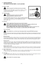
Page 22: ...scriptions locales de s curit ainsi que les instructions de s curit 1 3 Sources de danger Attention L installation JETSTREAM peut selon le type d appareil injecter par sa buse jectrice jusqu 780 litre...

Page 23: ...ateur est express ment averti que l appareil doit tre utilis exclusivement de mani re correcte c est dire selon le paragraphe 1 4 Utilisation correcte de l appareil En cas de mauvaise utilisation l ut...

Page 24: ...passer 35 C 2 3 Proposition de Montage MONTAGE DES PI CES SCELLER DANS LE COFFRAGE Montage fig 1 Proc der comme montr dans fig 1 Il faut monter la seconde MIRO2 pi ce sceller une distance lat rale de...

Page 25: ...a coupure et les trous dans la paroi de la piscine sont faciles faire l aide du cadre de serrage bouchon 2 niveau de l eau niveau de l eau pi ce sceller buse paroi cadre de serrage vis M6 joint planch...

Page 26: ...massage du dos ou lors de la fermeture intentionnelle de la buse et doit emp cher que de l eau ne jaillisse du tuyau d aspiration d air Une soupape est herm tiquement tanche tant que des cheveux ou a...

Page 27: ...pine cr pine 15 30 60 100 100 30 mesures en cm 8 9 11 10 19 20 23 1 2 3 4 5 6 7 12 13 14 15 16 17 22 21 18 24 Proposition de montage de JetStream MIRO dans une piscine en b ton sans goulotte d bordeme...

Page 28: ...rs le tuyau de l autre main Retirez alors le tuyau de la buse Massage localis Pour un massage localis de certaines parties du corps ou certains muscles utilisez le tuyau de massage Maintenez cet effet...

Page 29: ...op forte humidit no sont pas couvertes par Ia garantie 5 SERVICE L appareil ne doit tre utilis que lorsqu il se trouve en parfait tat Veiller ce que la maintenance et la v rification des installations...

Page 30: ...m A 3 Fusibles 400 V fusibles 16 A action retard e ou 16 AK coupe circuits automatiques 230 V monphas fusibles 20 A action retard e ou 16 AK coupe circuits automatiques 4 Puissance Le groupe moto pomp...

Page 31: ...5 1 3 5 13 A1 PE N L1 L2 L3 2 4 6 6 4 2 N 14 A2 Electric c ble 380 V 3N PE V Terre Disjuncteur Contacteur telerupteur Branchement de moteur Disjuncteur SCHEMA DE BRANCHEMENT A REALISER POMPES 3 5 kW o...

Page 32: ...32 ID NR 268 061 11 04 uwe GmbH Buchstra e 82 Postfach 2020 D 73510 Schw bisch Gm nd Tel 07171 103 0 Fax 07171 103 106...

Reviews: