6
Only use connection cables marked
H07RN-F
Connections and repairs to the
electrical equipment may only be
carried out by qualified electricians.
5.4 Dust connection
Before initial operation, the machine
must be connected to a dust extractor.
The suction should switch on
automatically when the planer is
switched on.
The flow rate on the suction port must
be 20m/sec.
Flexible hoses must be of non-
flammable quality, and must be
connected to the machine ground
system.
5.5 Starting operation
You can start the machine with the
green on button. The red button on the
main switch stops the machine.
In case of emergency push the E-stop
button to stop the machine.
Assure the correct direction of rotation
before you start any machining.
In case of overload the motor overload
cut-off will react. After approximately
10 minutes of cooling the machine
can be started again.
6. Machine operation
Correct operating position:
To feed the workpiece into the
machine, position yourselves offset to
one side of the feed opening.
Workpiece handling:
Adjust the planer table to the
workpiece thickness.
Feed workpiece slowly and straight
into the thicknesser. It will then be
automatically fed through the
thicknesser.
Guide workpiece straight through the
thicknesser.
To remove the workpiece from the
machine, position yourselves offset to
one side of the outfeed opening.
Support long workpieces with helping
roller stands.
Operating notes:
Always use sharp cutter knives!
Feed with thicker workpiece end at the
front, hollow side downward.
Max. 5mm depth of cut. If a workpiece
gets stuck lower the planer table by
app. 1crank turn (1,6 mm).
Plane the stock with the grain, if
possible.
You get a better surface when planing
several passes with less chip removal.
Switch machine off if no further
planning is to be done immediately
afterwards.
Workpieces shorter than 250mm may
not be processed.
The machine has a sectional infeed
roller and a sectional chip breaker to
allow multiple boards to be planed at
the same time.
7. Setup and adjustments
General note:
Setup and adjustment work may
only be carried out after the
machine is protected against
accidental starting by locking the
main switch or by pulling the mains
plug.
7.1 Adjusting Depth of Cut
Depth of cut is controlled by raising or
lowering the table.
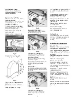
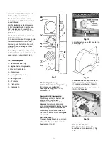
Loosen the lock knob (B, Fig 4).
Fig 4
Use the handwheel (A) to adjust.
One revolution equals to 1,6mm.
Retighten lock knob.
7.2 Adjusting Feed Speed
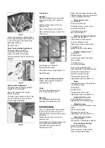
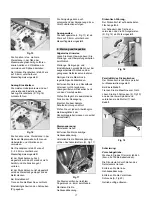
To adjust the feed speed, turn lever
while the planer is running (Fig 5)
Feed speed:
6m/min or 10m/min
Fig 5
7.3 Adjusting Table Rollers
The Planer has two table rollers (N,
Fig 11) which help reduce friction of
the workpiece on the table.
The table rollers should be set high
when planing rough stock, and set low
for finish cuts.
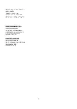
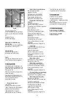
With a single lever (B, Fig 6) you can
raise the rollers.
Fig 6
The table rollers are adjusted at the
factory to be flat with the table
surface.
If they should need adjustment:
Disconnect machine from power
source to inspect.
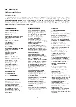
Adjust with the hex cap screws (E, Fig
7).
Fig 7


