background image


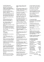
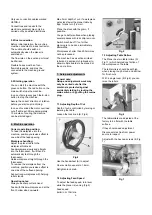
7.4 Changing cutter knives 

Risk of personal injury by cuts from 
the cutter knives. Wear suitable 
gloves when changing cutter knives. 


Knife Removal 

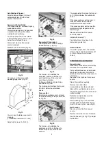
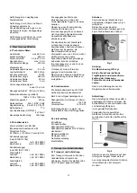
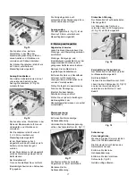
Turn the square-head bolts (A, Fig 9) 
of the cutter knife lock bar (B) all the 
way in (wear gloves!). 

Springs (D) will cause the knife to rise 
in the slot. 

At first remove cutter knife (C), then 
cutter knife lock bar from the cutter 
block. 


Fig 9 

Clean all surfaces of cutter block and 
cutter knife lock bar with a suitable 
solvent (do not use cleaning agents 
that could corrode the light metal 
components). 

Use only suitable cutter knives 
conforming the technical specification 
and EN 847-1 

Unsuitable, incorrectly mounted, dull, 
cracked of bent cutter knives can work 
loose or increase the risk of kickback 
considerably. 

Always replace all 4 cutter knives at 
once. 

The cutter knife lock bars are 
balanced to each other and thus can 
randomly be placed. 

Only cutter knives marked “HSS” or 
“HS” can be resharpened! 
When resharpening, remove the same 
amount of material from all three 
cutter knives, otherwise a balancing 
error may cause damage to the 
bearings. 

Cutter knives can only be resharpened 
down to a minimum width of 15 mm. 

Use genuine Jet replacement parts 
only. 

TIP:  
If a foreign object nicks the knives 
cutting edges 

Instead of changing the knives, simply 
axially offset the knives to each other. 

Move one knife up to 5mm to the right 
and another knife up to 5mm to the 
left of the cutterhead. 

Knife Installation and Adjustment


Any knife adjustment or replacement 
should be done to all four knives at 
the same time.  

Failure to do this may result in an out-
of-balance cutterhead and vibrations 
which can lead to bearing failure. 

Place the cutter knife lockbar in the 
cutterblock´s groove. Turn the 8 
square-head bolts so far that the 
cutter knife will just slide in. 

Insert a sharp cutter knife and adjust 
position with the cutter knife lockbar, 
so that neither protrudes over the 
edge of the cutter block. 

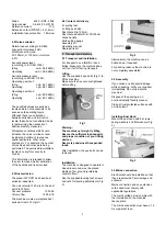
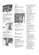
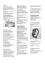
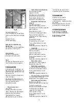
Place the knive-setting gauge on the 
cutterhead (Fig 10) 


Fig 10 

This will hold the high point of the 
knive to the proper height above the 
cutterblock. 
Springs (D, Fig 9) will cause the knife 
to rise in the slot. 

Use the gauge at both ends of the 
knife. 

Knive relationship must be held within 
0.03mm for accurate and smooth 
planing. 

To tighten the cutter knife, turn the 8 
square-head bolts of the cutter knife 
lockbar. 
Start tightening with the two outer 
bolts.  

At first halve tighten all 32 square-
head bolts, then repeat and fully 
tighten all bolts this time. 

Do not extend tool when tightening the 
bolts, do not tighten bolts by striking 
the wrench. 

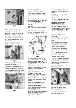
Close and lock the cutter block cover 
after knife changing has been 
completed (Fig 8). 

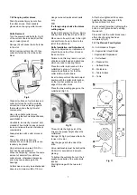
7.5 The Planer’s Feed System 

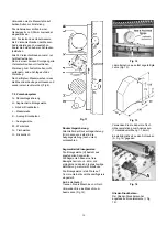
G…Anti Kickback Fingers 

H…Segmented Infeed Roller 

I…Segmented Chipbreaker 

J….Cutterhead 

K….Pressure Bar 

L….Outfeed Roller 

M….Workpiece 

N….Table Rollers 

O….Table 


Fig 11 


Summary of Contents for JWP-201

Page 1: ...hs from the date of purchase date of invoice Any further claims shall be excluded This warranty includes all guarantee obligations of the Seller and replaces all previous declarations and agreements concerning warranties The warranty period is valid for eight hours of daily use If this is exceeded the warranty period shall be reduced in proportion to the excess use but to no less than three months...

Page 2: ...d do not expose it to rain Wood dust is explosive and can also represent a risk to health Dust form some tropical woods in particular and from hardwoods like beach and oak is classified as a carcinogenic substance Always use a suitable dust extraction device Before machining remove any nails and other foreign bodies from the workpiece Never operate with the guards not in place serious risk of inju...

Page 3: ...eveling feet 2 Lifting eye bolts Dust chute Dia 125mm Dust chute adapter Dia 125 150mm Crank handle Knife setting gauge Assembly kit Operating manual Spare parts list 5 Transport and start up 5 1 Transport and installation For transport use a forklift or hand trolley Make sure the machine does not tip or fall off during transport Lifting Use the supplied 2 eye bolts Fig 1 to lift the machine Make ...

Page 4: ...rating notes Always use sharp cutter knives Feed with thicker workpiece end at the front hollow side downward Max 5mm depth of cut If a workpiece gets stuck lower the planer table by app 1crank turn 1 6 mm Plane the stock with the grain if possible You get a better surface when planing several passes with less chip removal Switch machine off if no further planning is to be done immediately afterwa...

Page 5: ...r Move one knife up to 5mm to the right and another knife up to 5mm to the left of the cutterhead Knife Installation and Adjustment Any knife adjustment or replacement should be done to all four knives at the same time Failure to do this may result in an out of balance cutterhead and vibrations which can lead to bearing failure Place the cutter knife lockbar in the cutterblock s groove Turn the 8 ...

Page 6: ...ece near the cutterhead to reduce snipe and to avoid board vibration The pressure bar has been factory set to 0 0 02mm below the cutterhead knives If the pressure bar is set too high it does not contact the machined workpiece and looses function If the pressure bar is set too low the workpiece will get stopped and not feed through Disconnect machine from power source to inspect Adjust with screws ...

Page 7: ...t the machine from the power source All protective and safety devices must be re attached immediately after completed cleaning repair and maintenance work Repair and maintenance work on the electrical system may only be carried out by a qualified electrician Motor doesn t start No electricity check mains and fuse Defective switch motor or cord consult an electrician Overload has reacted Wait and s...

Page 8: ...ontent Use the table rollers to reduce friction 10 Environmental protection Protect the environment Your appliance contains valuable materials which can be recovered or recycled Please leave it at a specialized institution 11 Available accessories Stock number 10000209 Set of 4 high speed steel HSS knives Stock number 709207 Foldable roller stand ...

Page 9: ...Monaten ab dem Verkaufsdatum Rechnungsdatum geltend gemacht werden Weitergehende Ansprüche sind ausgeschlossen Die vorliegende Garantie umfasst sämtliche Garantieverpflichtungen seitens des Verkäufers und ersetzt alle früheren Erklärungen und Vereinbarungen betreffend Garantien Die Garantiefrist gilt für eine tägliche Betriebszeit von 8 Stunden Wird diese überschritten so verkürzt sich die Garanti...

Page 10: ...en Sie dass auch Medikamente Einfluss auf Ihr Verhalten nehmen können Greifen Sie niemals in die laufende Maschine Die laufende Maschine nie unbeaufsichtigt lassen Vor dem Verlassen des Arbeitsplatzes die Maschine ausschalten Halten Sie Unbeteiligte insbesondere Kinder vom Gefahrenbereich fern Benützen Sie die Maschine nicht in der Nähe von brennbaren Flüssigkeiten oder Gasen Beachten Sie die Bran...

Page 11: ... Exposition die Raumcharakteristik andere Lärmquellen usw wie z B die Anzahl der Maschinen und andere benachbarte Bearbeitungsvorgänge Außerdem kann der zulässige Immissionspegel von Land zu Land unterschiedlich sein Trotzdem ist diese Information geeignet dem Anwender der Maschine eine bessere Abschätzung der Gefährdung und des Risikos zu ermöglichen 4 3 Staubemission Die Dickenhobelmaschine JWP ...

Page 12: ...haltet dieser selbsttätig ab Nach einer Abkühlzeit von ca 10 Minuten lässt sich die Maschine wieder einschalten 6 Betrieb der Maschine Richtige Arbeitsstellung Um das Werkstück in die Maschine einzuführen stellen Sie sich seitlich versetzt neben die Zuführöffnung Werkstückhandhabung Stellen Sie den Dickentisch auf Werkstückdicke ein Werkstück langsam und gerade einschieben Das Werkstück wird autom...

Page 13: ... dass immer alle 4 Hobelmesser zugleich ausgetauscht werden Die Messer Andruckleisten sind zueinander gewuchtet und können beliebig eingesetzt werden Nur Hobelmesser mit der Aufschrift HSS oder HS dürfen nachgeschliffen werden Beim Nachschleifen alle Hobelmesser in gleichem Maße nachschleifen sonst können durch Unwucht Lagerschäden auftreten Hobelmesser dürfen nur bis zu einer Breite von 15 mm nac...

Page 14: ...le K Auszug Druckbalken L Auszugswalze M Werkstück N Tischwalzen O Dickentisch Fig 11 Rückschlagsicherung Alle Greifer der Rückschlagsicherung G müssen von selbst in die Ausgangsstellung nach unten zurückkehren Segmentierte Einzugswalze Die Einzugswalze H besteht aus angefederten Segmenten Die Segmente haben eine freie Beweglichkeit von ca 6mm und ermöglichen dadurch die gleichzeitige Beförderung ...

Page 15: ...iten grundsätzlich nur bei ausgeschaltetem Antrieb und bei gezogenem Netzstecker vornehmen Reinigen Sie die Maschine in regelmäßigen Zeitabständen Entfernen Sie Harz und Rückstände mit einem nicht brennbaren Lösungsmittel vom Dickentisch und von den Vorschubwalzen Prüfen Sie täglich die ausreichende Funktion der Absaugung Ersetzen Sie beschädigte Schutzeinrichtungen sofort Prüfen Sie vor jedem Arb...

Page 16: ...me zu hoch in mehreren Durchgängen hobeln Gegen die Faser gearbeitet Werkstück von der Gegenrichtung bearbeiten Werkstück inhomogen Werkstück Feuchte zu hoch Auszug Druckbalken ist zu hoch eingestellt Druckbalken einstellen Kapitel 7 5 Hobelstufe Unzureichende Werkstückführung Rollbock verwenden stumpfe Hobelmesser Scharfe Hobelmesser einsetzen Auszug Druckbalken ist zu hoch eingestellt Druckbalke...

Page 17: ...te de la vente date de la facture Toute autre prétention est exclue La présente garantie comprend toutes les obligations de garantie incombant au vendeur et remplace toutes les déclarations et conventions antérieures en termes de garanties Le délai de garantie s applique pour une durée d exploitation de huit heures par jour Au delà le délai de garantie diminue proportionnellement au dépassement ma...

Page 18: ...ion des extincteurs Préserver la machine de l humidité et ne jamais l exposer à la pluie La poussière de bois est explosive et peut être nocive pour la santé Les poussières de certains bois exotiques et de bois durs tels que le hêtre et le chêne sont classées comme étant cancérigènes Utiliser un collecteur de poussières afin d éviter une production de poussières trop élevée Retirer les clous et au...

Page 19: ...uée 1350 Pa Volume 1200 m h Ainsi une paramètre de concentration de 2 mg m est assuré 4 4 Contenu de la livraison 4 pieds réglables 2 anneaux de manutention Buse d aspiration Ø125mm Adaptateur pour buse d aspiration Ø 125 150mm Manivelle Instruction pour le réglage des fers Accessoires pour le montage Mode d emploi Liste pièces de rechange 5 Transport et mise en exploitation 5 1 Transport Pour le ...

Page 20: ...ntroduire la pièce doucement et tout droit dans la machine La pièce rentre automatiquement Passer la pièce tout droit dans la machine Pour retirer la pièce de la machine se positionner décalé sur le côté de la sortie de la table Pour des pièces longues utiliser des supports roulants Conseils Ne travailler qu avec des fers bien coupants Le bout plus épais de la pièce passe d abord dans la machine l...

Page 21: ... brèche sur les 4 fers Au lieu de changer les fers il suffit souvent de les déplacer axialement Déplacer un fer jusqu à 5 mm sur la droite et un autre jusqu à 5 mm sur la gauche par rapport à la broche Montage et réglage des fers Toujours changer tous les fers en même temps Tous les fers doivent être aiguisés de la même façon donc avoir la même largueur afin d éviter tout déséquilibre et des dégât...

Page 22: ...églage peut s effectuer par la vis A Fig 14 Fig 14 Barre de pression articulée La barre de pression articulée I Fig 15 se compose d éléments séparés sur ressorts Fig 15 Ceci permet de conduire en même temps plusieurs pièces d oeuvre près de l arbre ainsi que d éviter les déchirures et les vibrations et de dévier les copeaux La barre de pression articulée est réglée au départ usine à 0 8 mm au dess...

Page 23: ...ères de guidage R Fig 18 sont réglées au départ usine Fig 18 Parallélisme de la table de rabotage La table de rabotage est réglée au départ usine parallèlement à l arbre des fers Si un réglage est nécessaire Déconnecter la machine du réseau Desserrer les trois vis S Fig 19 sur une des deux broches et faire tourner l écrou T comme nécessaire Fig 19 Graissage Engrenage d entraînement Changer l huile...

Page 24: ...ce déformée Fers montés de travers ou en biais Fixer les fers à l aide du module de réglage Pièce coincée Epaisseur de rabot trop grande Faire plusieurs passages La barre de pression extractible est trop basse Régler la barre de pression chapitre 7 5 Réglage difficile de la table Graissage insuffisant Graisser les broches et le guidage Avance difficile de la pièce La courroie du moteur glisse Ress...

Reviews: