5
Mains
400V ~3/PE 50Hz
Output power
5,6 kW (7,5 HP) S1
Reference current
11 A
Extension cord (H07RN-F): 4x1,5mm²
Installation fuse protection
16A slow
4.2 Noise emission
Determined according to EN 860
(Inspection tolerance 4 dB)
Workpiece pine wood:
W=100mm, L=1000mm, moisture
8,5%
Acoustic power level
(according to EN ISO 3746):
Idling
LwA 96,8 dB(A)
Operating
LwA 100,6 dB(A)
Acoustic pressure level
(according to EN ISO 11202):
Operating position 1:
Idling
LpA 86,1 dB(A)
Operating
LpA 85,1 dB(A)
Operating position 2:
Idling
LpA 85,8 dB(A)
Operating
LpA 85,7 dB(A)
The specified values are emission
levels and are not necessarily to be
seen as safe operating levels.
Although there is a correlation
between emission and immission
levels, these do not constitute a basis
for determining the necessity of
additional safety measures.
Workplace conditions which could
influence the noise immission level
include the duration of resonance,
spatial particulars, other noise
sources etc. For example, the number
of machines and other work being
performed. The permissible workplace
levels can vary from country to
country.
This information is intended to allow
the user to make a better estimation
of the hazards and risks involved.
4.3 Dust emission
The planer JWP-201 has been dust
emission inspected.
At an air velocity of 20 m/s on the dust
port dia 150mm:
Vacuum pressure
1350 Pa
Volume flow
1200 m³/h
The machine meets a workplace dust
emission limit of 2 mg/m³.
4.4 Content of delivery
4 Leveling feet
2 Lifting eye bolts
Dust chute Dia 125mm
Dust chute adapter Dia 125/150mm
Crank handle
Knife setting gauge
Assembly kit
Operating manual
Spare parts list
5. Transport and start up
5.1 Transport and installation
For transport use a forklift or hand
trolley. Make sure the machine does
not tip or fall off during transport.
Lifting:
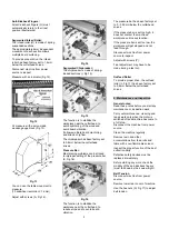
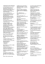
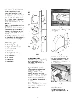
Use the supplied 2 eye bolts (Fig 1) to
lift the machine.
Make sure the hex nuts are tightened
before lifting.
Fig 1
Warning:
The machine net weight is 615kg
Assure the sufficient load capacity
and proper condition of your lifting
devices.
Never step underneath suspended
loads.
After installation, the eye bolts can be
removed.
Installation:
The machine is designed to operate in
closed rooms and must be placed
stable on firm ground (preferably
concrete floor).
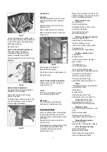
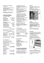
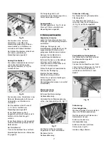
Use the supplied leveling feet, screws
and nuts for leveling adjustments (Fig
2).
Fig 2
Alternatively, the machine can be
bolted down if required.
For packing reasons the machine is
not completely assembled.
5.2 Assembly
If you notice any transport damage
while unpacking, notify your supplier
immediately. Do not operate the
machine!
Dispose of the packing in an
environmentally friendly manner.
Clean all rust protected surfaces with
a mild solvent.
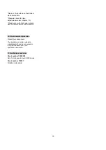
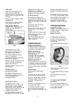
Installing Dust Hood
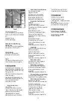
Mount the dust hood with 8 screws,
spring washers and flat washers (Fig
3).
Fig 3
5.3 Mains connection
Electricals should be installed so that
they are protected from damage and
exposure.
Mains connection and any extension
cords used must comply with
applicable regulations.
The mains voltage must comply with
the information on the machine
licence plate.
The mains connection must have a 16
A surge-proof fuse.


