


9
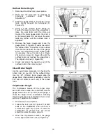
Extension Tables
1. Mount an extension table to the edge of the
main table with three M8 x 25 hex cap
screws and washers (Figure 7) using a
12mm wrench. Do not fully tighten yet.
2. The extension table must be leveled with the
main table. Place a straight edge (such as a
carefully jointed board, or a steel bar) across
the extension table and the main table.
Move the straight edge to various points
along the table during the procedure.
NOTE: The straight edge should not lie over
the raised table rollers, as this would distort
the leveling process. Either place the
straight edge just short of the table rollers, or
lower the table rollers completely into the
table (see page 12) until the extension
tables have been installed.
3. Insert three socket set screws below the hex
cap screws, using a 4mm hex wrench, and
screw them in or out as needed until tables
are level.
4. Securely tighten the hex cap screws.
5. Mount the second extension table to the
opposite side of the planer table, using the
same procedure.
Dust Hood
Mount the hood to the rear of the head casting
with six M6 x 12 hex washer head screws (A,
Figure 8).
It is strongly recommended that you use a dust
collection system with this planer. If you are not
using a dust collection system, do not attach the
dust hood to the planer, as the accumulation of
dust inside the hood may create a safety hazard,
or eventually cause jamming of the roller system
in the cutterhead.
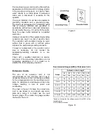
Grounding Instructions
Electrical connections must
be made by a qualified electrician in
compliance with all relevant codes. This
machine must be properly grounded to help
prevent electrical shock and possible fatal
injury.
In the event of a malfunction or breakdown,
grounding provides a path of least resistance for
electric current to reduce the risk of electric
shock.
Figure 7
Figure 8
Summary of Contents for JWP-15DX
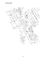
Page 23: ...23 Head Assembly ...
Page 26: ...26 Base Assembly ...
Page 28: ...28 Table Assembly ...
Page 30: ...30 Gear Box Assembly ...
Page 32: ...32 Stand and Motor Assembly ...
Page 34: ...34 Electrical Connections ...
Page 35: ...35 ...


