


10
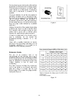
This machine’s power cord must be fitted with an
appropriate UL/CSA listed 230 Volt plug (similar
to the one shown in Figure 9), or it can be “hard-
wired” directly to a control panel. If hard-wired,
make sure a disconnect is available for the
operator.
If a plug is installed, it must have an equipment-
grounding conductor and a grounding prong.
The plug must be plugged into a matching outlet
that is properly installed and grounded in
accordance with all local codes and ordinances.
Do not modify the plug – if it will not fit the outlet,
have the proper outlet installed by a qualified
electrician.
Improper connection of the equipment-grounding
conductor can result in a risk of electric shock.
The conductor with insulation having an outer
surface that is green with or without yellow
stripes is the equipment-grounding connector.
If repair or replacement of the electric cord or
plug is necessary, do not connect the
equipment-grounding conductor to a live
terminal.
Check with a qualified electrician or service
personnel if the grounding instructions are not
completely understood, or if in doubt as to
whether the tool is properly grounded.
Extension Cords
The use of an extension cord is not
recommended for this machine, but if one is
necessary make sure the cord rating is suitable
for the amperage listed on the machine's motor
plate. An undersize cord will cause a drop in line
voltage resulting in loss of power and
overheating.
The chart in Figure 10 shows the correct size
cord to use based on cord length and motor
plate amp rating. If in doubt, use the next
heavier gauge. The smaller the gauge number
the heavier the cord.
Figure 9
Recommended Gauges (AWG) of Extension Cords
Extension Cord Length *
Amps
25
feet
50
feet
75
feet
100
feet
150
feet
200
feet
<
5
16 16 16 14 12 12
5
to
8 16 16 14 12 10 NR
8
to
12 14 14 12 10 NR NR
12
to
15 12 12 10 10 NR NR
15 to 20
10
10
10
NR
NR
NR
21
to
30 10 NR NR NR NR NR
*based on limiting the line voltage drop to 5V at 150% of the
rated amperes.
NR: Not Recommended.
Figure 10
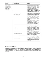
Summary of Contents for JWP-15DX
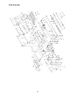
Page 23: ...23 Head Assembly ...
Page 26: ...26 Base Assembly ...
Page 28: ...28 Table Assembly ...
Page 30: ...30 Gear Box Assembly ...
Page 32: ...32 Stand and Motor Assembly ...
Page 34: ...34 Electrical Connections ...
Page 35: ...35 ...


