


17
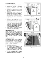
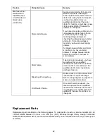
Chip Deflector
The chip deflector (C, Figure 27) keeps wood
chips from falling into the outfeed roller. The
deflector should be set approximately 1/16" to
1/8” from the tip of the knives. Make sure the
deflector is oriented so the bevel on its front
edge matches the shape of the cutterhead.
Feed Speed Control
Your machine is equipped with a spiral, serrated
infeed roller and a solid steel outfeed roller.
When the feed rollers are engaged, they turn to
feed the stock. The feed rollers slow
automatically when the machine is under heavy
load for best planing in all conditions. The feed
rollers are driven by chains and sprockets (see
Figure 28) which take power directly from the
cutterhead through the oil bath gear box. The
drive chain does not need tensioning, as a
tension device (Figure 28) maintains proper
tension at all times.
To gain access to the chain and sprockets (for
example, when performing maintenance)
proceed as follows:
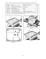
1. You may find it easier to remove the
sprocket guard by first removing the
handwheel from the machine, though this is
not mandatory.
2. Remove the socket head cap screw from the
center of the cover using a 6mm hex
wrench. Remove the left triangular back
plate (2 screws) using a 10mm wrench. See
Figure 29.
3. Pull the sprocket guard off the machine.
NOTE: Always re-install cover before operating
planer.
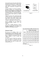
The gear box has two feed speeds. These are
set by pulling out or pushing in the shift lever
(Figure 30). Always change feed speed while the
machine is running. A label showing the lever
positions is affixed just above the lever. It is also
shown in Figure 30.
Do not attempt to change
feed speed while stock is passing through
the machine. Damage to the gearbox may
result.
Stock Return Rollers
The two rollers on top the machine serve as a
convenient rest for stock. They save time and
motion for the operator as the stock is returned
to the infeed side.
Figure 28
Figure 29
Figure 30
Figure 31
Summary of Contents for JWP-15DX
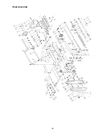
Page 23: ...23 Head Assembly ...
Page 26: ...26 Base Assembly ...
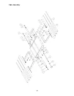
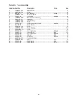
Page 28: ...28 Table Assembly ...
Page 30: ...30 Gear Box Assembly ...
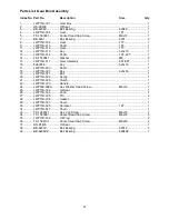
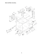
Page 32: ...32 Stand and Motor Assembly ...
Page 34: ...34 Electrical Connections ...
Page 35: ...35 ...


