17
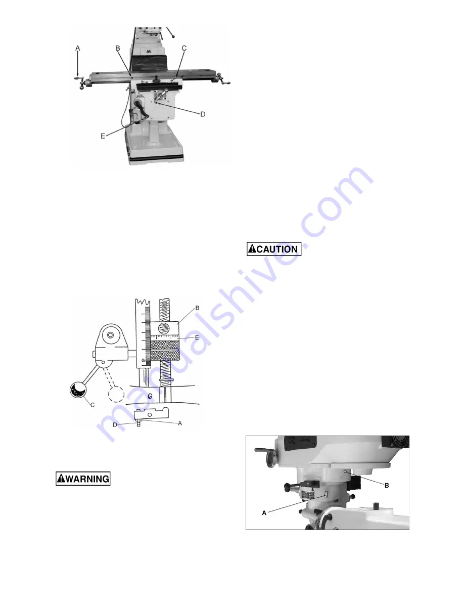
Figure 13: Table movement
12.10
Feed Trip Adjustment
Refer to Figure 14.
1. Loosen lock nut (A, Figure 14).
2. Engage trip handle (C) by pulling away from
head assembly.
3. Adjust micro nuts (E) against quill stop (B).
4. Slowly turn adjusting screw (D) until lever (C)
trips.
5. Tighten lock nut (A).
Figure 14: Feed trip adjustment
13.0
Maintenance
Always disconnect machine
from power source before doing any
maintenance. If you do not have the knowledge
or training to complete the maintenance, have
an authorized JET service center maintain your
mill. Failure to comply may cause serious
bodily injury.
13.1
General maintenance
During operation, occasionally vacuum and
brush chips and debris from machine.
Periodically operate knee and table lead
screws through full range of movement to
evenly distribute lubricant (particularly when
applied using the “one-shot” system).
Periodically apply light machine oil to work
table and other exposed metal surfaces to
prevent rust or corrosion.
Periodically remove vent panels to check
pulleys and belts for unusual wear or grooving.
Operators should vary speed occasionally to
prevent formation of grooves on the pulley
surfaces.
When using a coolant pump, periodically clean
the sump in the machine base to extend pump
life and promote efficient cutting. Change
coolant regularly at intervals recommended by
the coolant supplier.
13.2
Lubrication
Do not operate mill before
lubricating the machine fully. Failure to comply
may cause damage to machine.
Refer to figures 15 and 16 for areas of the mill to
lubricate:
Spindle Bearings (A, Figure 15) – fill oil cup
once daily with Mobil DTE® Oil Light or
equivalent.
Zerk fitting for back gear (B, Figure 15) – Insert
Mobilith AW1, or equivalent, weekly when
operating in back gear mode.
Oil Pump (C, Figure 16) – fill reservoir as
needed by removing cap on top of tank and
filling with Mobil Vactra® #2 oil or equivalent.
Pump oil with release handle once for every
hour of operation. Way surfaces and
leadscrews are lubricated in this manner.
Knee leadscrew (D, Figure 16) – lubricate with
Mobilith AW2, or equivalent, once weekly.
Figure 15: Lubrication points
Summary of Contents for JTM-1050
Page 7: ...7 6 0 JTM 1050 Installation Layout Figure 1 ...
Page 22: ...22 14 1 1 JTM 1050 Variable Speed Head Assembly Exploded View ...
Page 25: ...25 14 2 1 JTM 1050 Head Assembly Exploded View ...
Page 29: ...29 14 3 1 JTM 1050 Base Assembly Exploded View ...
Page 32: ...32 14 4 1 JTM 1050 Table Leadscrew Assembly Exploded View ...


