13
clutch becomes engaged. Neutral position is
between forward and reverse position.
(Refer to Figure 8 and accompanying text
for further detail.) If control does not engage
easily, move handwheel (J) back and forth
to aid engagement.
It is recommended that
feed direction knob be left in neutral
position when not in use.
L.
Quill stop
(L) – located on front of head.
Used to disengage automatic feed in either
direction as well as the setting point for
working to a given depth.
M.
Quill feed speed selector
(M) – located on
left side of head. Pull knob out and locate
handle over choice of three feed speeds
(0.0015”, 0.003”, and 0.006”) per spindle
revolution.
The
selector
shifts
into
engagement more easily when the spindle
is rotating.
N.
On/Off/Reverse switch
(N) – located on left
side of head. Turns spindle on and off, and
changes rotation direction of spindle.
O.
Drawbar
(O) – located on top of head. Used
to secure tool holder in the taper. Use the
spindle brake (C) while tightening drawbar.
11.0
Operating precautions
Do not attempt to change spindle RPM while
motor is stopped. Only change spindle speeds
while motor is running.
Verify that spindle brake is released before
starting motor.
Rotate spindle by hand to facilitate meshing of
clutch and gears.
Do
not
use quill automatic feed at speeds
above 2700 RPM.
It is recommended that the auto feed worm
gear be disengaged whenever auto feed is not
required. This will avoid unnecessary wear on
the worm gear.
Maximum auto feed loading is a 3/8” (9.5mm)
diameter bit for drilling in mild steel. Use
manual feed for bits larger than 3/8".
Overload clutch is factory set to hold up to 200
lbs. down feed pressure on the quill
(accommodates drills up to 3/8"). Do
not
attempt to adjust clutch pressure.
12.0
Adjustments
12.1
Drawbar operation - changing
tooling
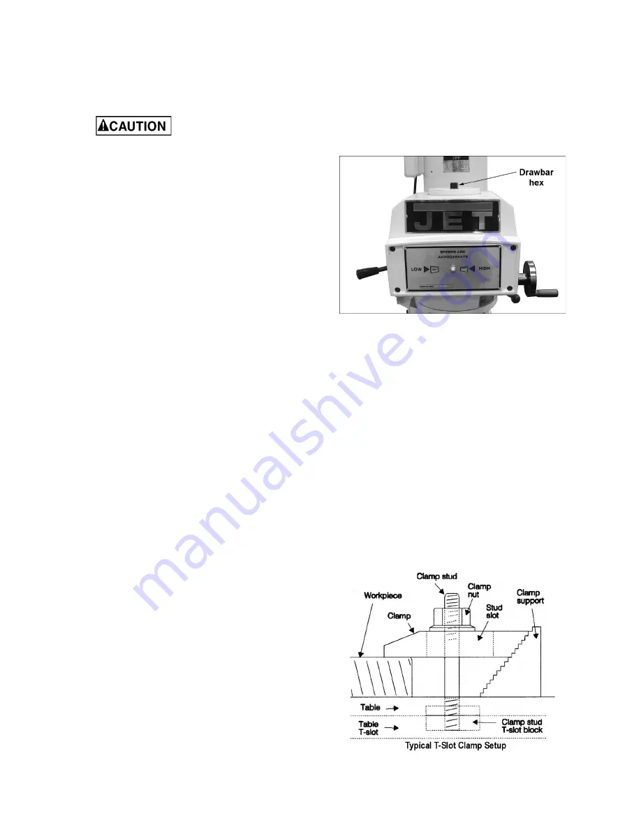
1. Apply the spindle brake and loosen the draw
bar two or three turns (counterclockwise) with
the provided wrench placed over the draw bar
hex (Figure 6).
Figure 6: Drawbar
2. Tap the top of the draw bar with a soft-faced
hammer to loosen the collet from the taper.
3. Remove the tool from the collet.
4. Insert the tool you are going to use into the
collet.
5. Tighten the draw bar firmly using the provided
wrench with spindle brake applied. The tool is
now ready for use.
12.2
Clamping workpiece to table
The worktable has 5/8-inch T-slots for clamping
work piece to table.
1. Set switch to OFF position.
2. Place work piece on table.
3. Clamp work piece using T-slot clamps, studs,
and step blocks as required. See Figure 7.
Figure 7: Work piece clamping
Summary of Contents for JTM-1050
Page 7: ...7 6 0 JTM 1050 Installation Layout Figure 1 ...
Page 22: ...22 14 1 1 JTM 1050 Variable Speed Head Assembly Exploded View ...
Page 25: ...25 14 2 1 JTM 1050 Head Assembly Exploded View ...
Page 29: ...29 14 3 1 JTM 1050 Base Assembly Exploded View ...
Page 32: ...32 14 4 1 JTM 1050 Table Leadscrew Assembly Exploded View ...


