


8
Applicability of the following instructions will depend upon your choice of accessories. Call-out numbers are
those in the parts breakdown, sect. 11.0.
5.4
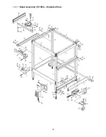
Stand assembly
See Figure 5-6.
1. Mount support bars (2 long, 2 short) to legs (#4). Mount lower braces (2 long, 2 short) to legs. Position JET
logo toward front of stand.
2. Install levelers (#19). These can be adjusted for height at any time to make the stand level and
accommodate use of the wheels and swivel caster. Tighten leveler hex nut against stand.
3. Install wheels (#12) with brackets, and swivel caster (#14) with its bracket.
4. Mount power switch with bracket (#10) and storage hook assembly (#42) to legs.
Figure 5-6
2
2
3
3
4
4
7
5
6
8
14
19
20
20
21
21
22
21
25
27
30
20
21
26
21 20
22 21
21
41
41
41
6
12
10
42
Summary of Contents for JRL-912
Page 16: ...16 11 1 1 Router Lift Assembly 737000 Exploded View ...
Page 18: ...18 11 2 1 Stand Assembly 737004 Exploded View ...
Page 26: ...26 This page intentionally left blank ...
Page 27: ...27 This page intentionally left blank ...
Page 28: ...28 427 New Sanford Road LaVergne Tennessee 37086 Phone 800 274 6848 www jettools com ...


