


10
5.7
Fence assembly
See Figure 5-8.
1. Attach a rail base (#12) to each side of table with socket head cap screws (#18). Hand tighten only.
2. Slide a scale (#15) into each rail (#13). Slide square nuts (#16) into channel of base, and mount rails to
bases with hex cap screws (#19) and flat washers (#17). Attach rails so they are flush with back edge of
table. Make adjustments as needed, then tighten screws on bases (#18).
3. Carefully align zero mark on scale with inscribed line at edge of table (see Figure 5-9). This is best done
using a steel straight edge or carefully jointed piece of wood laid across entire width of table and along the
inscribed lines. Tighten knob to fix scale position. Repeat for other side.
4. Slide hex nut (#7) into rail channel (#13) and mount fence (#1) using handles (#2) and washers (#5).
5. Install sub-fences (#9), router bit guard (#10) and dust port (#32) as shown. Attach dust hose to port with
clamp.
Figure 5-8
9
10
11
4
12
13
15
16
18
17
19
20
5
6
1
2
5
6
4
5
7
32
Summary of Contents for JRL-912
Page 16: ...16 11 1 1 Router Lift Assembly 737000 Exploded View ...
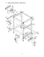
Page 18: ...18 11 2 1 Stand Assembly 737004 Exploded View ...
Page 26: ...26 This page intentionally left blank ...
Page 27: ...27 This page intentionally left blank ...
Page 28: ...28 427 New Sanford Road LaVergne Tennessee 37086 Phone 800 274 6848 www jettools com ...


