


6
5.0
Setup and assembly
Read and understand the
entire contents of this manual before
attempting assembly or operation! Failure to
comply may cause serious injury!
5.1
Unpacking and cleanup
1. Remove all contents from shipping carton. Do
not discard cartons or packing material until
product
is
assembled
and
running
satisfactorily.
2. Inspect contents for shipping damage. Report
any damage to your distributor.
3. Compare contents of shipping carton with the
contents list below. Report shortages, if any, to
your distributor.
5.2
Shipping contents
See Figures 5-1 thru 5-5.
Box #1
Cast iron table
1 Router table, cast iron
6 Socket head cap screws, M6x16
6 Lock washers M6
6 Flat washers M6
10 Socket flat head screws, M6x20
10 Hex nuts M6
OR…
MDF table
1 Router table, MDF/Melamine
10 Socket flat head wood screws M7x40
32 Phillips pan hd. wood screws 3/16” x 5/8”
Box #2
Router Lift Assembly
1 Router Lift
2 Crank handle
1 Pin wrench
1 Router adaptor, 3-1/4 in.
1 Router adaptor, 3-1/2 in.
4 Hex wrenches, 3,4,6,8 mm
2 Socket hd flat screws M6x30
1 Starter pin with screw
1 Insert ring, 38.1mm
Box #3
Dust Collection Box Assembly
1 Front panel with door
1 Left panel
1 Right panel
1 Rear panel
1 Bottom panel
1 Dust port
1 Dust hose with clamps
6 Hex cap screws M6x12
6 Flat washers M6
6 Lock washers M6
3 Pan hd. machine screws M4x10
26 Pan hd. machine screws M4x6
Box #4
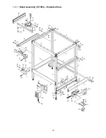
Stand Assembly
4 Leg tubes
4 Support bars – 2 long, 2 short
4 Lower braces – 2 long, 2 short
1 Miter gauge assembly
1 Switch assembly
1 Swivel caster assembly
2 Wheels
2 Wheel brackets
1 Tool holder assembly
4 Levelers
2 Bit storage racks
2 Hex cap screws M8x50
2 Lock nuts M8
6 Flat washers, M8
4 Socket hd cap screws M6x16
4 Flat washers M6
40 Hex cap screws M6x12
40 Flat washers M6
2 Pan hd mach screws M4x20
4 Hex nuts M4
Box #5
Fence Assembly
1 Dust port
1 Guard
1 Fence
2 Fence faces
2 Side bracket bases
2 Side brackets
1 Miter gauge fence
2 Lock handles with nuts
8 Lock knobs with T-bolts
10 Flat washers M8
2 Fence spacers
8 Socket hd cap screws, M6x12
6 Hex cap screws 1/4x5/8
6 Flat washers M6
6 Square nuts 1/4
2 Wing nuts M6*
2 Flat washers M6*
2 Hex cap screws M6x30*
(* packaged inside miter gauge fence)
5.3
Tools required for assembly
Cross-point (Phillips) screwdriver
Hex wrenches 4, 6, 8mm
Open-end wrenches 10,12,14 mm
(
NOTE: A ratchet wrench with sockets will speed
assembly time.)
Figure 5-1a: Box #1 Cast Iron Table
Summary of Contents for JRL-912
Page 16: ...16 11 1 1 Router Lift Assembly 737000 Exploded View ...
Page 18: ...18 11 2 1 Stand Assembly 737004 Exploded View ...
Page 26: ...26 This page intentionally left blank ...
Page 27: ...27 This page intentionally left blank ...
Page 28: ...28 427 New Sanford Road LaVergne Tennessee 37086 Phone 800 274 6848 www jettools com ...


