22
If you exceed 9 amps current draw a thermal
overload switch in the electrical control panel will
trip. If this occurs, locate and reset the thermal
switch.
8.23
Tapping operations
1. Determine the most efficient tapping speed
(spindle speed) by consulting appropriate
machinist's tables, your tap supplier, coolant
supplier and/or workpiece supplier.
2. Be certain that feed rate dial is at neutral.
See Section 8.10
Setting feed rate
.
3. Turn on spindle motor. Also, turn on the
coolant pump if coolant is being used.
4. Move arm/spindle control lever to
Forward
.
5. Use the feed levers to move the tap into its
pilot hole until the tap makes its initial thread
cut and is engaged in the work piece.
6. Allow the tap to "self feed" into the pilot hole
until it has completed its tapping operation.
7. Move arm/spindle control lever to neutral
and allow spindle to stop completely.
8. Move arm/spindle control lever to reverse,
so that tap unscrews itself from the hole it
has just threaded.
8.24
Arm/spindle control lever
The four-position arm/spindle control lever is
located on the left hand side of the drill head
console. See Figure 10. It controls spindle
rotation direction and raising and lowering of the
arm.
The ability to control the height of the arm is
available when:
1. The main power to the machine is ON at its
branch service panel.
2. The emergency STOP switch is disengaged.
3. The arm/spindle control lever is pushed up
or down.
4. The column and arm UNLOCK button (right
hand side of the drill head –
see Figure 10
)
is pressed to disengage the machine locks.
NOTE: The control lever does not return to
neutral when released, but remains in position.
This means unless you return it to neutral, the
arm will keep raising or lowering until it contacts
a limit switch.
9.0
Adjustments
After extended use – usually several years – the
radial arm drill may require adjustment of certain
parts. Two areas require particular attention:
•
The clamping device.
•
The gap between head and rail.
9.1
Clamping Device
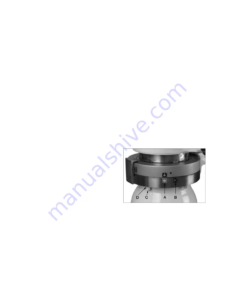
If there is backlash in the clamping device,
correct as follows.
Refer to Figure 14.
1. Press and hold the
unlock button
(see
Figure 10) until the arrow (Figure 14) points
to “B”. Release the button. The clamping
device is now disengaged.
2. Loosen the five
locking nuts
(C).
3. Turn the five upper
adjusting nuts
(D)
counterclockwise (i.e. tighten them up
against the clamping ring) approximately
180°.
4. Re-tighten the five locking nuts (C).
5. Press and hold the
lock button
until the
arrow returns to (A). The clamping device is
now engaged.
Figure 14
6. Move arm/spindle control lever to Arm UP.
7. Press emergency stop button after the arm
has elevated a short distance.
8. Press the unlock button to release the
clamping device.
9. Adjust the nut (E, Figure 15) one notch
clockwise.
10. Move arm/spindle control lever to neutral.
11. Reset emergency stop button.
Summary of Contents for J-1230R
Page 11: ...11 General Features and Terminology cont Figure 4 Figure 5 ...
Page 16: ...16 7 0 Operating Controls Figure 10 Operating Controls ...
Page 27: ...27 Figure 17 Figure 18 Figure 19 Figure 20 Figure 21 ...
Page 30: ...30 13 2 1 Column and Base Exploded View ...
Page 32: ...32 13 3 1 Arm Front Exploded View ...
Page 34: ...34 13 4 1 Arm Rear and Clamping Gearbox Exploded View ...
Page 38: ...38 13 6 1 Gearbox Assembly Head Exploded View ...
Page 42: ...42 13 7 1 Rear of Head I Exploded View ...
Page 45: ...45 14 0 Electrical Connections for J 1230R ...
Page 47: ...47 ...


