background image


Operating Instructions and Parts Manual 

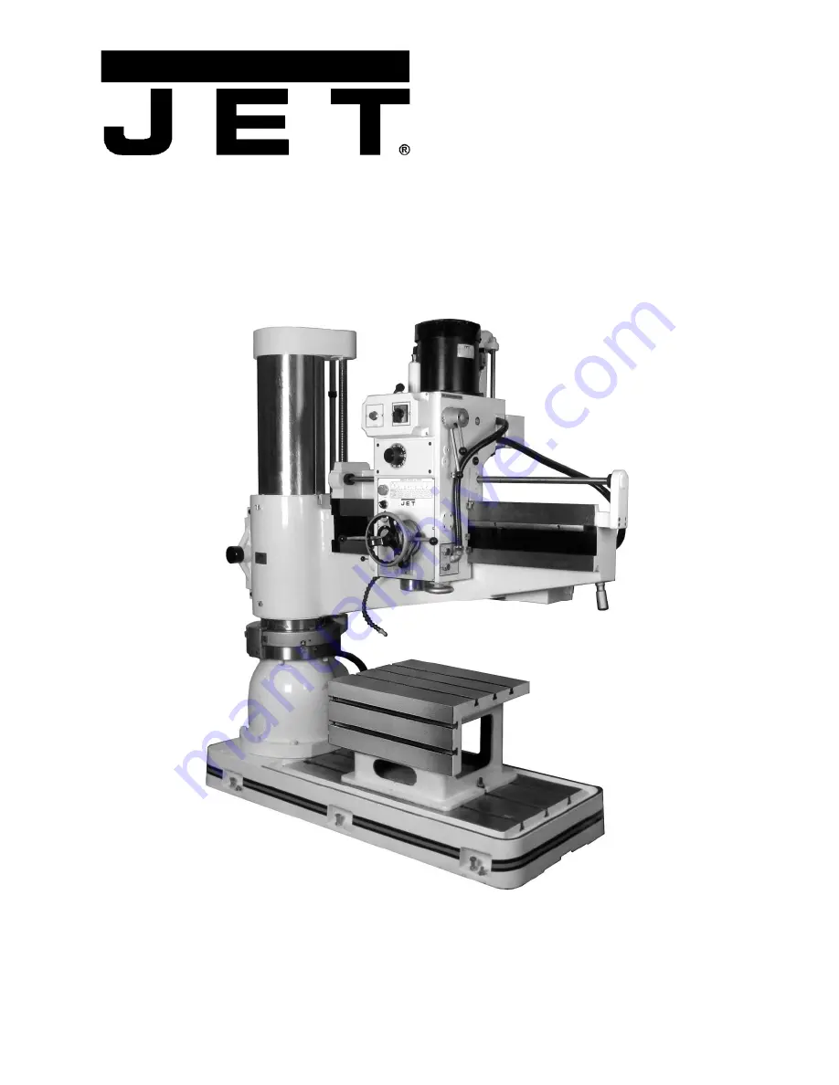
4-ft. Radial Arm Drill Press 

Models J-1230R, J-1230R-4 


WALTER MEIER (Manufacturing) Inc. 

427 New Sanford Road 
LaVergne, Tennessee 37086 

Part No. M-320036


Ph.: 800-274-6848 

Revision B


07/2011 

www.waltermeier.com 

Copyright © 2011 Walter Meier (Manufacturing) Inc. 

Summary of Contents for J-1230R

Page 1: ...ft Radial Arm Drill Press Models J 1230R J 1230R 4 WALTER MEIER Manufacturing Inc 427 New Sanford Road LaVergne Tennessee 37086 Part No M 320036 Ph 800 274 6848 Revision B 07 2011 www waltermeier com Copyright 2011 Walter Meier Manufacturing Inc ...

Page 2: ...stage prepaid to a location designated by us For the name of the location nearest you please call 1 800 274 6848 You must provide proof of initial purchase date and an explanation of the complaint must accompany the merchandise If our inspection discloses a defect we will repair or replace the product or refund the purchase price at our option We will return the repaired product or replacement at ...

Page 3: ...ting spindle speed 18 8 9 Feed rate and depth of cut 19 8 10 Setting feed rate 19 8 11 Setting depth of cut using power feed system 20 8 12 Spindle direction and power feed 20 8 13 Hand feed roughing operations 20 8 14 Fine hand feed using power feed system 20 8 15 Tapping 21 8 16 Power ON OFF 21 8 17 Power ON light 21 8 18 Coolant control 21 8 19 Spindle motor controls 21 8 20 Turning off spindle...

Page 4: ...I Parts List 43 13 8 1 Counterweight Assembly Exploded View 44 13 8 2 Counterweight Assembly Parts List 44 14 0 Electrical Connections for J 1230R 45 14 1 Electrical Connections for J 1230R Parts List 46 Familiarize yourself with the following safety notices used in this manual This means that if precautions are not heeded it may result in minor injury and or possible machine damage This means tha...

Page 5: ... ANSI Z87 1 specifications Use of eye wear which does not comply with ANSI Z87 1 specifications could result in severe injury from breakage of eye protection 2 Wear proper apparel No loose clothing or jewelry which can get caught in moving parts Contain long hair Rubber soled footwear is recommended for best footing 3 Do not overreach Failure to maintain proper working position can cause you to fa...

Page 6: ...e securely locked to the column before operating the drill press This must always be checked prior to starting the machine 3 Always use the correct tooling Tooling shall always be maintained and properly sharpened All tooling must be run at the proper speeds and feeds as they apply to the job Use only recommended accessories and follow those manufacturer s instructions pertaining to them Tooling s...

Page 7: ...n controls 110V Spindle motor model J 1230R TEFC 5 3 HP 3 7 2 2kW 3 PH 230V only 13 18 A 60Hz Spindle motor model J 1230R 4 TEFC 5 3 HP 3 7 2 2kW 3 PH 460V only 6 6 7 5 A 60Hz Spindle taper Morse No 4 Spindle speeds twelve speeds within 45 1550 RPM Quill spindle travel 9 7 8 in 247mm Quill spindle travel with powerfeed engaged 9 7 16 240mm Spindle travel along arm total 35 in 875mm Feed rates dist...

Page 8: ...m gasoline chemical substances dust acid sulfides magnetic interference and explosive environments 5 Keep machine away from electrical interference sources such as welding machines and EDM Electric Discharge Machining 6 Illumination of work area should be greater than 500lux 7 Work area must have adequate ventilation 4 3 Power Supply Requirements 1 Acceptable voltage fluctuation normally 10 2 Acce...

Page 9: ...he specifications in this manual were current at time of publication but because of our policy of continuous improvement Walter Meier reserves the right to change specifications at any time and without prior notice without incurring obligations ...

Page 10: ...rm 15 Arm Rotation Handle 16 Work Lamp 17 Fine Feed Handwheel 18 Spindle 19 Work Lamp Toggle Switch 20 Electrical cabinet 21 Counterweight System 22 Clamping Rod 23 Guard Panel 24 Clamping Gear 25 Coolant Pump 26 Arm Raising Motor 27 Clamping Motor 28 Clamping Gearbox 29 Elevating Worm Gear Reducer 30 Arm Rail 31 Caution Label High Voltage p n CL HV 32 Warning Label Tipping Risk p n J1230R WL 33 C...

Page 11: ...11 General Features and Terminology cont Figure 4 Figure 5 ...

Page 12: ... 6 Figure 4 shows spacing for the 360 rotational path of the arm plus 1000mm approx 40 inches of general maintenance area on each side Distance column center to arm limit Maintenance area A Total space required B 1546mm 61 in 1000mm 40 inches 5092mm 200 in Figure 7 ...

Page 13: ...d to your distributor Read the instruction manual thoroughly for assembly maintenance and safety instructions Contents of Shipping Container Figure 9 1 Radial Arm Drill Press not shown 6 Leveling Pads 1 Tool Box containing 1 Grease gun 1 Oil bottle 1 Tapered Drift 1 Adjustable wrench 1 Set of hex keys 1 Flat blade screwdriver 1 Cross point screwdriver 1 Instructions and Parts Manual not shown 1 Wa...

Page 14: ... and possible injury or death to the machine operator and bystanders 7 Connect the electrical service branch to the machine according to the instructions which follow in section 6 4 Electrical Connections This work should be done only by a qualified and licensed electrician who is familiar with machine service and national and local codes 8 Turn on the drill press see Section 8 0 Operation push th...

Page 15: ...he box The transformer can be connected to either a 230 or 460 volt source and its taps are labeled for voltage By locating the source tap on the transformer you will be able to determine the branch voltage required A service disconnect is recommended The use of fuses or circuit breakers for each of the voltage supply wires is required Use fuses or circuit breakers which are appropriate to the vol...

Page 16: ...16 7 0 Operating Controls Figure 10 Operating Controls ...

Page 17: ...ever in the OFF position before inserting or removing tooling To insert tooling 1 Verify that machine is disconnected from power 2 Be certain the spindle is clean free from oil and ready to accept the shank of any tooling 3 Check the shank of the tooling to be certain the tooling is free from dirt nicks or burrs If nicks or burrs are discovered file or stone the shank until it is smooth 4 Be certa...

Page 18: ...sired position on the arm and if no other adjustments to spindle location are required push the LOCK button to secure all machine locks NEVER swing the drill press arm on the support column unless you are absolutely certain the drill press base is firmly attached to the shop floor If the arm is moved off its position directly above the base and the base is not bolted to the floor THE DRILL MAY TIP...

Page 19: ...el This system is designed to prevent gearbox damage if the power feed mechanism is engaged damage which would occur if the quill were to bottom out against the upper or lower limit of quill travel In the event of failure of either limit switch there is also a safety clutch mechanism which will slip when travel limits are reached However while you are able to use virtually the full travel of the q...

Page 20: ... need to make deeper holes you must do the machining in steps Power feed is used only for drilling not for threading Feed rate must be set off neutral for power feed to be engaged 8 12 Spindle direction and power feed Spindle rotation direction is managed by the arm spindle control lever on the left hand side of the drill head See Figure 10 Clockwise or forward rotation is the direction of rotatio...

Page 21: ...motor controls Power to spindle motor is controlled as follows 1 The cutout box control lever must be in the ON position 2 The motor speed control switch must be in either HI or LOW position 3 The Emergency Stop switch must be disengaged 4 The arm spindle control lever must be engaged for selected rotation See Section 8 24 Arm spindle control lever 8 20 Turning off spindle drive To turn power OFF ...

Page 22: ...its branch service panel 2 The emergency STOP switch is disengaged 3 The arm spindle control lever is pushed up or down 4 The column and arm UNLOCK button right hand side of the drill head see Figure 10 is pressed to disengage the machine locks NOTE The control lever does not return to neutral when released but remains in position This means unless you return it to neutral the arm will keep raisin...

Page 23: ...and rotate the bearing shaft Rotate handwheel on the front of the head it should be snug but still easily turned 4 Tighten set screws G 5 Repeat steps 1 through 4 for opposite side of the head 6 Back at the original side of head loosen set screws I 7 Insert hex key into hole J and rotate bearing shaft Test the handwheel tightness again When satisfied retighten set screws I 8 Repeat steps 6 and 7 f...

Page 24: ...24 10 0 Spindle Speed Chart Note A similar chart is found on the front of the drill head Table 3 ...

Page 25: ...maller drill bit or lower feed rate consult appropriate feed and speed rate tables Feed rate too fast Operation not in compliance with speed and feed rate tables Table 4 If drill bit gets broken in the spindle 1 Move arm spindle control lever to neutral 2 Press emergency stop button 3 Push the head gearbox out of the way 4 Pinch the end of the broken bit with pliers 5 Rotate counterclockwise and p...

Page 26: ... Oil Cup for spnidle Top of drill head Add lubricant to full capacity Daily Mobil Vactra oil AA 11 Oil Cups 2 for head arm contact Right side of drill head Add lubricant to full capacity Daily Mobil Vactra oil AA 12 Arm Raising Worm Gear Rear of column Top off at fill hole 12a Fill to sight glass full level 12b Check sight glass daily Mobil Vactra oil AA Replace annually drain at 12c Use sight gla...

Page 27: ...27 Figure 17 Figure 18 Figure 19 Figure 20 Figure 21 ...

Page 28: ...r reach our service department call 1 800 274 6848 Monday through Friday see our website for business hours www waltermeier com Having the Model Number and Serial Number of your machine available when you call will allow us to serve you quickly and accurately 13 1 1 Riser Mechanism Exploded View ...

Page 29: ...232631 Oil Level Gauge 4 22 M0604006 Plug PT1 4 1 23 5232651 Bearing 30303 2 24 5232661 Bearing Cover 1 25 5232671 Socket Head Cap Screw M6x14L 1 26 J 5232681 Top Cap 1 27 TS 1505051 Socket Head Cap Screw M10 x 35L 1 28 5232691 Nut M24 6 29 5232711 Key 6mm x 20L 1 30 5232721 Lead Screw 1 31 TS 1533042 Phillips Pan Head Machine Screw M5 x 12L 1 32 10415 Compression Cover 2 33 M1401 M6x65 Socket Hea...

Page 30: ...30 13 2 1 Column and Base Exploded View ...

Page 31: ...ver 1 19 TS 1505051 Socket Head Cap Screw M10 x 35L 4 20 5232971 Thrust Bearing 51111 1 21 5232961 Top Bearing Cover 1 22 5232951 Bolt 1 2 12N x 3 L 1 23 5233271 Locking Shaft 1 24 5233251 Key 6mm x 30L 1 25 TS 1524021 Set Screw M8 x 10L 2 26 5233211 Shaft 1 27 5233141 Key 6mm x 30L 1 28 5233221 Bushing 1 29 J 5233231 Locking Bracket 1 30 TS 1524021 Set Screw M8 x 10L 2 31 5233261 Clamping Gear 1 ...

Page 32: ...32 13 3 1 Arm Front Exploded View ...

Page 33: ... 10032 Key 1 59 M1425001 Pan Head Socket Screw 3 16 x 3 8 L 6 60 10250 Upper Compression Cover 1 61 10798 Upper Compression Cover notched 1 62 J1230R 462 Lower Compression Cover 2 63 M1425001 Pan Head Socket Screw 3 16 x 3 8 L 6 64 5233391 Oil Cup PT1 8 x 90 2 65 5233331 Work Lamp FS51441 1 65A 5233341 Lamp Seat 1 66 5233311 Acrylic Lamp Cover 1 67 5513357 Phillips Pan Head Machine Screw 3 16 x 3 ...

Page 34: ...34 13 4 1 Arm Rear and Clamping Gearbox Exploded View ...

Page 35: ...5236371 Bearing 6009ZZ 1 24 5236351 Retainer R75 1 25 5236331 Gear 1 26 TS 1524021 Set Screw M8 x 10L 1 27 J 5236221 Bushing 1 28 5236231 Cover 1 29 M1414006 Pan Head Socket Screw 3 16 x 3 8 L 3 30 5236261 Locking Shaft 1 31 5236271 Bushing 1 32 TS 1523031 Set Screw M6 x 10L 2 33 5236291 Bushing 1 34 J 5236311 Block 1 35 TS 15404061 Socket Head Cap Screw M8 x 30L 4 36 J 5236321 Arm 1 37 5236621 Ar...

Page 36: ... 63 10314W Gear Box Cover 1 64 5236461 Gear 1 65 5236441 Bushing 1 66 10315 Washer 1 67 5236531 Shaft 1 68 5236521 Key 5mm x 18L 1 69 5236541 Key 6mm x 30L 1 70 5236561 Gear 1 71 TS 1524021 Set Screw M8 x 10L 1 72 5236491 Block 1 73 TS 1505041 Socket Head Cap Screw M10 x 30L 2 74 TS 1523021 Set Screw M6 x 8L 1 75 J1230R WL Warning Label Tipping Risk not shown 5 1 4 W x 8 1 4 H 1 ...

Page 37: ...rew M6 x 16L 4 4 5232321 90 Degree Elbow PT1 4 x PS1 4 x 90 1 5 5232271 Hose PT3 8 x 130 L 1 6 5232411 Male Connector PT3 8 x PS3 8 1 7 5232341 90 Degree Elbow 3 8 x 90 1 8 5232371 Tube 3 8 x 15 L 1 9 5232351 Tube Sleeve 2 10 5232391 Knurled Screw M10 x 25L 2 11 5232421 Brass Valve 3 8 1 12 5232431 Coolant Hose 3 8 x 450L 1 13 M1315017 Tube Holder UC 5 2 14 5513357 Phillips Pan Head Machine Screw ...

Page 38: ...38 13 6 1 Gearbox Assembly Head Exploded View ...

Page 39: ...ep Speed Change Lever Short 1 23 10324 Three Step Speed Change Lever Long 1 24 5234871 Plastic Knob 3 8 2 25 5234661 Oil Seal TC30 x 45 x 8mm 1 26 5234741 O Ring P12 1 27 5234671 Speed Change Rocker Arm 1 28 5234681 Copper Block 1 29 5234621 Spindle Change Shaft 1 30 5234711 Copper Block 1 31 5234721 Speed Change Rocker Arm 1 32 TS 1524021 Set Screw M8 x 10L 4 33 5234741 O Ring P12 1 34 5234031 Fe...

Page 40: ...04ZZ Ball Bearing 6004ZZ 1 81 5234361 Gear Shaft 1 82 5234371 Key 6mm x 85L 2 83 5234351 Key 6mm x 10L 2 84 5234341 Retaining Ring S35 1 85 5234331 Gear 1 86 5234321 Gear 1 87 5234311 Gear 1 88 5234281 Gear 1 89 BB 6004ZZ Ball Bearing 6004ZZ 1 90 5234261 Crown Washer AW04 1 91 5234251 Lock Nut 1 92 5234141 Ball Bearing 6007UU 1 93 5234131 Washer 1 94 M1312 R62 Retaining Ring R62 1 95 5234121 Ball ...

Page 41: ...1 Socket Head Cap Screw M5 x 12L 4 141 5235261 Bearing Housing 1 142 5235311 Key 6mm x 20L 1 143 5235321 Pinion Shaft 1 144 5235121 Key 4mm x 12L 1 145 BB 6204ZZ Ball Bearing 6204ZZ 1 146 BB 6005ZZ Ball Bearing 6005ZZ 1 147 5235331 Helical Tooth Gear 1 148 TS 1503051 Socket Head Cap Screw M6 x 20L 1 149 5233871 Feed Speed Selector 1 150 5233841 Bolt M10 x 16L 1 151 5233851 Spring 1 152 5233861 Ste...

Page 42: ...42 13 7 1 Rear of Head I Exploded View ...

Page 43: ...Bearing 6205ZZ 2 9 5235711 Eccentric Shaft 2 10 5235651 Bolt M10 x 110L 2 11 TS 1525011 Set Screw M10 x 10L 4 12 5235461 Adjustable Collar 2 13 5235671 Bushing 2 14 BB 6205ZZ Bearing 6205ZZ 2 15 5235641 Eccentric Shaft 2 16 J 5235491 Cam Shaft Sleeve 1 17 5235481 Cam Shaft 1 18 J 5235511 Bearing Bracket 1 19 J 5235561 Aluminum Plate 1 20 TS 1502041 Socket Head Cap Screw M5 x 16L 3 21 5235421 Eccen...

Page 44: ...er 2 3 5235771 Oil Seal TC19 x 32 x 8 2 4 5235781 Round Bar 2 5 5235791 Washer 1 2 2 6 5235811 Nut 1 2 4 7 5235831 Socket Head Cap Screw M8 x 120L 4 8 J 5235841 Chain Frame 1 9 5235911 Retainer E9 4 10 10376 Collar 2 11 5235931 Bearing TA1015Z 2 12 10376 Collar 2 13 5235941 Shaft 2 14 5235961 Chain 3 8 x 130 1 15 5235971 Bolt 1 16 5235981 Chain Adapter 1 17 J 5235991 Cast Iron Block 1 ...

Page 45: ...45 14 0 Electrical Connections for J 1230R ...

Page 46: ...eed Change A441 CA10 1 E1701002 WL Work Lamp FS 51441 1 E1202011 PB1 Push Button YKϕ22 110V 1a1b R 1 E1202003 PB2 Push Button YKϕ22 110V 1a1b G 1 E1618001 PB3 Emergency Push Button SBT 307 1 E2303006 L Control Light SP301 110V White 1 E2303003 PL Power Light SP301 110V Red 1 E0207016 OL1 Overload Relay for 230V RHN 10 3 5 4 8A 1 E0207016 OL2 Overload Relay for 230V RHN 10 3 5 4 8A 1 E0207036 OL3 O...

Page 47: ...47 ...

Page 48: ...48 WALTER MEIER Manufacturing Inc 427 New Sanford Road LaVergne Tennessee 37086 Phone 800 274 6848 www jettools com www waltermeier com ...

Reviews: