background image

JRV212T

4

INSTALLATION

Before You Begin

1.

Disconnect Battery

Before you begin, always disconnect the battery negative terminal.

2.

Remove Transport Screws

 and discard.

Important Notes

Before final installation, test the wiring connections to make sure the unit is connected properly 
and the system works.

Use only the parts included with the unit to ensure proper installation. The use of unauthorized 
parts can cause malfunctions.

Consult with your nearest dealer if installation requires the drilling of holes or other 
modifications to your vehicle.

Install the unit where it does not interfere with driving and cannot injure passengers if there is a 
sudden or emergency stop.

If the installation angle exceeds 30º from horizontal, the unit might not give optimum 
performance.

Avoid installing the unit where it will be subject to high temperatures from direct sunlight, hot 
air, or from a heater, or where it would be subject to excessive dust, dirt or vibration.

2-DIN Front Mount

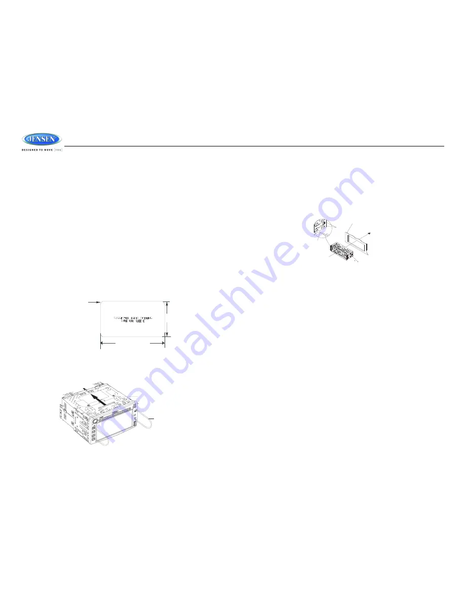
This unit can be installed in a dashboard with an opening of the following dimensions:

1.

Slide the mounting sleeve off of the chassis if it has not already been removed. If it is locked 
into position, use the removal keys (supplied) to disengage it. Insert the keys through the holes 
in the front panel as far as they will go, and then slide the sleeve off the back of the unit.

2.

Check the dashboard opening size by sliding the mounting sleeve into it. If the opening is not 
large enough, carefully cut or file as necessary until the sleeve easily slides into the opening. 
Do not force the sleeve into the opening or cause it to bend or bow. Check that there will be 
sufficient space behind the dashboard for the radio chassis.

3.

Locate the series of bend tabs along the top, bottom and sides of the mounting sleeve. With 
the sleeve fully inserted into the dashboard opening, bend as many of the tabs outward as 
necessary to firmly secure the sleeve to the dashboard.

4.

Place the radio in front of the dashboard opening so the wiring can be brought through the 
mounting sleeve.

5.

Follow the wiring diagram carefully and make certain all connections are secure and insulated 
with crimp connectors or electrical tape to ensure proper operation. 

6.

After completing the wiring connections, reconnect battery and turn the unit on to confirm 
operation (vehicle ignition switch must be on). If the unit does not operate, recheck all wiring 
until the problem is corrected. Once proper operation is achieved, turn the ignition switch off 
and proceed with final mounting of the chassis.

7.

Carefully slide the radio into the mounting sleeve making sure it is right-side-up until it is fully 
seated and the spring clips lock it into place.

8.

Test radio operation by referring to the operating instructions for the unit.

Removing the Unit

To remove the radio after installation:
1.

Make sure the ignition is turned off, and then disconnect the cable from the vehicle’s battery 
negative (-) terminal.

2.

Insert the removal keys straight into the holes on the front of the unit, as far as they will go. 

3.

Pull the radio straight out. 

7 1/4 inches

4 3/8 inches

1/16 inch max

(4 corners)

MOUNTING SLEEVE

REMOVAL KEY

TABS

SCREWDRIVER

MOUNTING SLEEVE

DASHBOARD

Summary of Contents for JRV212T

Page 1: ...JRV212T Installation and Operation Manual TOUCH PANEL MOBILE AUDIO AND OBSERVATION SYSTEM JRV212T...

Page 2: ...kills and ability required to properly perform installation Professional installation is recommended SiriusXM shall have no liability for damage injury resulting from the installation use of any Siriu...

Page 3: ...iquids or any other solvent Be sure to use only round CDs for this unit and do not use any special shape CDs Use of special shape CDs may cause the unit to malfunction Do not stick paper or tape on th...

Page 4: ...ntil the sleeve easily slides into the opening Do not force the sleeve into the opening or cause it to bend or bow Check that there will be sufficient space behind the dashboard for the radio chassis...

Page 5: ...NNECTOR CH3 CAMERA CONNECTOR CH2 CAMERA CONNECTOR CH1 CAMERA CONNECTOR YELLOW VIDEO INPUT FEMALE CONNECTOR 4 PIN PLUG AMP CONNECTOR RIGHT REAR SPEAKER RIGHT FRONT SPEAKER LEFT FRONT SPEAKER LEFT REAR...

Page 6: ...JRV212T 6 Recommended Camera Installation Configurations...

Page 7: ...o adjust the settings for that option See System Menu on page 9 Camera CAM Press the CAM button 5 to access camera mode Press and hold to view the System Menu Camera setup options See Camera Configura...

Page 8: ...el 12 or to the AUX IN cables on the back of the radio Video input is accessible for the R AUX mode through the VIDEO IN cable at the back of the unit 2 Touch the F AUX front AUX or R AUX rear AUX but...

Page 9: ...ion On Off Off System Menu Key Beep Off Button Backlight Auto Set Clock 1 13PM Sirius Satellite Radio only appears when SIRIUS tuner is connected See SIRIUS Satellite Radio on page 9 Weather Alert Con...

Page 10: ...et when it was last turned off Otherwise you can choose a default turn on level between 1 40 Clear SAME Codes OK Clear SAME Codes CANCEL Cancel and return to menu SAME Code 1 7 See SAME Decoding and F...

Page 11: ...n screen PRESET button to view the list of preset stations Six numbered preset stations for the current band are listed on the touch screen and can be selected when touched The selected station is dis...

Page 12: ...ssic Rock Adult Hits Soft Rock Top 40 Country Oldies Soft Nostalgia Jazz Classical Rhythm and Blues Soft R B Language Religious Music Religious Talk Personality Public College Weather Emergency Test E...

Page 13: ...the weather alert function automatically switches from any of the available function modes Tuner SIRIUS CD iPod AUX to Weather Band when the selected NOAA warning type is received detected See System...

Page 14: ...tion If you live near the border between counties you may want to receive alerts from more than one tower Your radio is capable of being programmed with up to 7 different FIPS location codes The defau...

Page 15: ...nformation bar at the top of the screen NOTE After loading a USB device files and folders are accessed in the order in which they were written to the device Therefore the playing order may not be the...

Page 16: ...of files Items with a folder icon to the left of the text are folders directories Touch to view the contents of the folder Use the button to move up a folder level NOTE Only five tracks are displayed...

Page 17: ...p down the channel list Touch a channel name to tune to that channel Direct Channel Access 1 Touch the DIRECT button to access the direct entry screen 2 Use the up down arrows to select the first digi...

Page 18: ...IUS Satellite Radio on page 9 Channel Lock Access Channel Lock through the System Menu under the SIRIUS Satellite Radio menu See SIRIUS Satellite Radio on page 9 1 Select Set Lock Code 2 No channels c...

Page 19: ...uously recharge when connected to the unit as long as the vehicle ignition is turned on Selecting a Playlist 1 When an iPod is playing touch the DIR button to display the playlists on the LCD 2 Use th...

Page 20: ...is not triggered the front audio output will be the from the last audio source played Rotate the VOL control 1 to adjust the volume of the audio source When Camera 1 is triggered and the Auto Mic Ena...

Page 21: ...latively close to the ignition system engine This type of noise can be easily detected because it will vary in intensity of pitch with the speed of the engine Usually the ignition noise can be suppres...

Page 22: ...The operation keys do not work The built in microcomputer is not operating properly due to noise Press the RESET button Sound skips The installation angle is more than 30 degrees Adjust the installat...

Page 23: ...ity S N 30dB 4 V Image Rejection 45 dB Stereo Separation 25dB AM MW Frequency Range USA 520 1710KHz Frequency Range Europe 522 1620KHz Sensitivity S N 20dB 36 dB General Operating Voltage DC 12 Volts...

Page 24: ...JRV212T 24 ASA Electronics Corporation www asaelectronics com www jensenrvdirect com 2012 ASA Electronics Corporation v 020912...

Reviews: