USER MANUAL
JEFCIND270L-10.0
270L
BELT DRIVEN AIR COMPRESSOR
•
10HP
•
10Bar
•
415V
~
50Hz (3)
USER MANUAL
JEFCIND270L-10.0
270L
BELT DRIVEN AIR COMPRESSOR
•
10HP
•
10Bar
•
415V
~
50Hz (3)
www.jeffersontools.com
www.jeffersontools.com
12
13
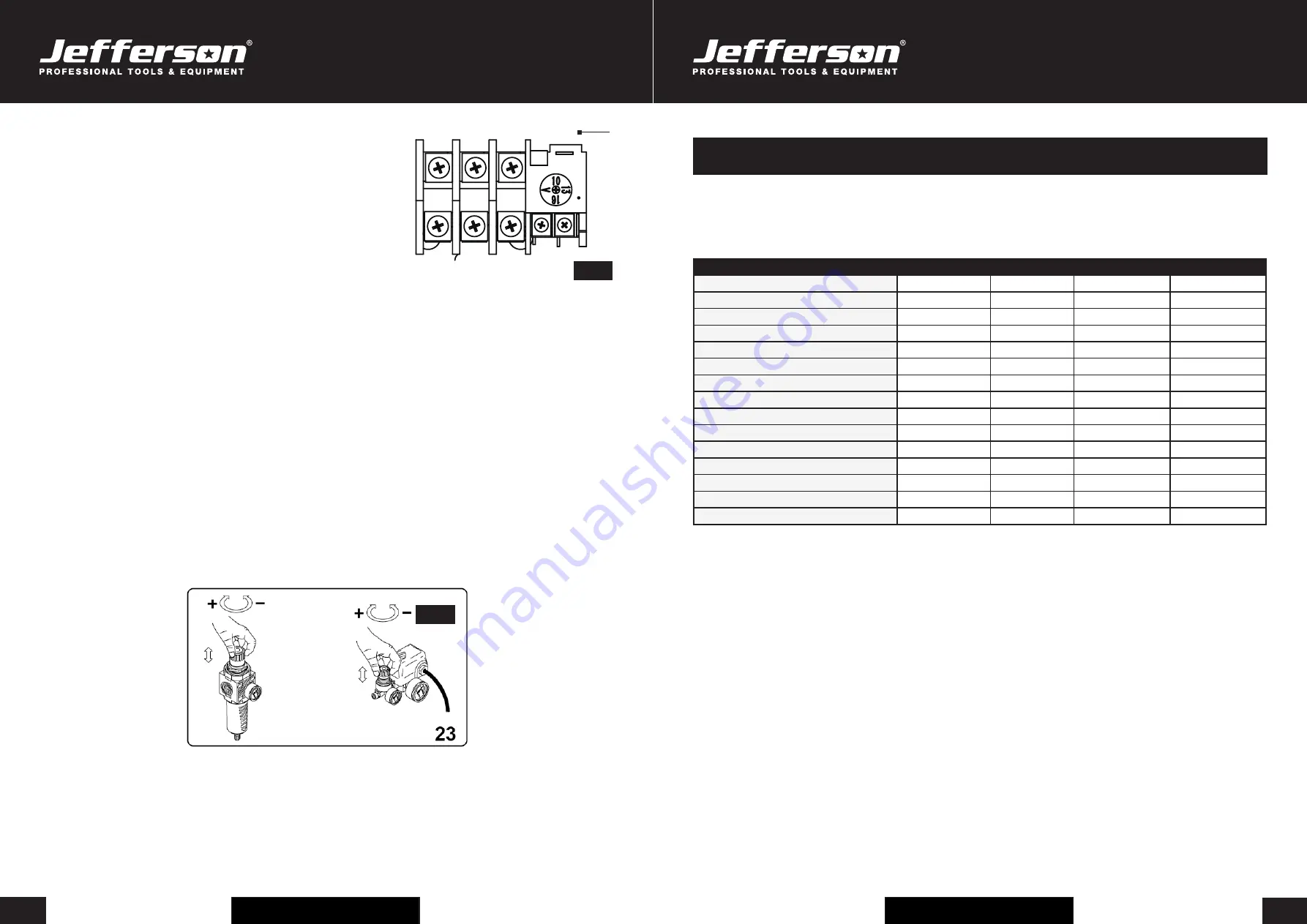
OVERLOAD CUT OUT
The compressor is equipped with an overload cut out (
E
) (
Fig.9
) which operates as a safety device
to protect the motor.
Should a fault occur and begin to overheat the motor the overload cut out will automatically
operate, cutting power.
This prevents damage occurring to the motor.
Allow 5 minutes for the machine to cool prior to attempting to reset the overload cut out (
E
) .
Press button. If after restarting the overload cut out is activated again, switch off the machine,
disconnect the power supply and contact your Jefferson Dealer for advice.
NOTE:
For technical specifications and detailed instructions please refer to the instructions provided with the specific air tool/accessory.The outlet
line pressure from the tank is adjusted using regulator. Rotate the regulator clockwise to increase the pressure or anticlockwise to decrease.
The pressure is indicated on gauge.
ATTENTION:
After each use set the pressure to zero to help prolong \the life of the regulator and avoid damage.
AIR LINE CONNECTION:
The compressor comes equipped with a quick in line female connector. To insert a male connector, pull the collar
backwards and insert the male connection. When fully inserted, release the collar. If a different style of connection is required the connector can be
replaced.
NOTE:
When fitting the replacement ensure the threads are sealed with PTFE tape for an air tight union.
ADJUSTING THE OPERATING PRESSURE
You do not have to use the maximum operating pressure at all times. On the contrary, the pneumatic tool being used often requires less pressure.
On compressors supplied with a pressure reducer, operating pressure must be correctly adjusted.
Release the pressure reducer knob by pulling it up, adjust pressure to the required value by turning the knob clockwise to increase pressure and
anti-clockwise to reduce it. When you have obtained optimum pressure, lock the knob by pressing it downward (
Fig.10
). For pressure reducers
equipped without a pressure gauge, the set pressure can be seen on the graduated scale located on the reducer body. On pressure reducers
equipped with a pressure gauge, pressure can be seen on the gauge itself.
WARNING:
Some pressure regulators do not have "push to lock", therefore simply turn the knob to adjust the pressure.
Fig.9
Fig.10
E
Before attempting any maintenance jobs on the compressor, make sure of the following:
1.
The master power switch is tuned off and equipment is isolated from the mains supply.
2.
Pressure switch and the control unit switches are all in the
OFF
position.
3.
All pressure has been removed from the air tank.
Procedure
Daily / Weekly
100Hrs
200Hrs
400Hrs
Check pump oil level
•
Drain condensate water from the tank
•
Check for unusual noise and vibration
•
Inspect equipment for air leaks
•
Check air filters
•
Inspect belts
•
Replace air filters
•
General cleaning
•
Check safety relief valve
•
Check belts for wear / replace
•
Check and tighten all bolts
•
Check tubes fittings & electrical connections
•
Service pump / engine
•
Internal & external tank inspection
•
Replace the oil
•
Changing / Filling Compressor Pump Oil
•
Ensure the compressor is turned off and disconnected from the power source.
•
Allow the compressor pump and other parts to cool off (if changing oil after use).
•
Ensure compressor is on a flat and level surface.
•
Remove fill cap / plug and place collection container underneath the oil drain cap.
•
Remove the oil drain cap, and let the oil drain out.
•
Replace the oil cap and be sure to tighten this nut securely (you can use some PTFE tape on the thread to help create a tighter seal before
tightening).
•
Fill the oil reservoir with a compatible compressor oil (e.g
Jefferson HT68 Compressor Oil
).
Checking / Cleaning the Air Filter
•
Ensure the compressor is turned off and disconnected from the power source.
•
Allow the compressor pump and other parts to cool off (if changing filter after use).
•
Unscrew the filter top from the filter base by turning (generally) counter-clockwise (the direction may vary depending on your filter).
•
Separate the filter top cover from the base.
•
Remove the filter element from the filter base.
•
Blow out dust and debris from the filter element.
•
Replace air filter element if required.
•
Reconnect filter top to the base and secure filter.
MAINTENANCE


