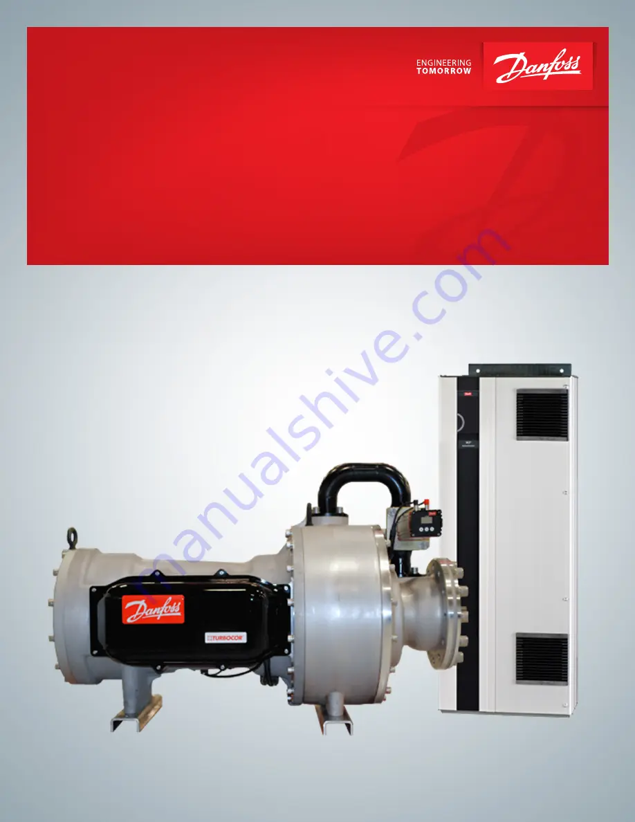
Variable Twin Turbo Centrifugal
Compressors
VTT Series
VTT880, VTT1000, VTT1200
Applications and Installation Manual
http://turbocor.danfoss.com
Page 1: ...Variable Twin Turbo Centrifugal Compressors VTT Series VTT880 VTT1000 VTT1200 Applications and Installation Manual http turbocor danfoss com ...
Page 2: ...Page 2 of 73 M AI VT 001 EN Rev C 1 THIS PAGE INTENTIONALLY LEFT BLANK ...
Page 3: ...etic Compatibility EMC Considerations 20 Electrical and Fire Hazard Protection 20 Drive Module Cooling 20 Cooling Fans 20 Drive Module Technical Specifications 21 Motor Cable Sizing 21 Electronic Control System 21 System Interface Connections 22 Compressor Control Module CCM Board 25 Pulse Width Modulator Amplifier PWM Board 25 Compressor Interface Module CIM Board 26 Sensor Monitoring 27 Step Mot...
Page 4: ...Physical Data of the VTT Compressor 42 Compressor Module 42 Drive Module 46 DC DC Converter Dimensions 50 Installations Guidelines 51 Safety Summary 51 Unpacking and Inspection 51 Required Tools 52 Compressor Module Installation 53 Rigging Requirements 53 Clearance 54 Compressor Installation Instructions 54 Drive Module Installation 56 Safety 56 Planning the Installation 56 Pre Installation Checks...
Page 5: ...erlock 65 Drive Module Serial Communications 66 Drive Module Installing Control Cables 66 Drive Module RS 485 Bus Termination 67 LED Cover Description 68 Access to Control Terminals 68 Fieldbus Connection 68 Electrical Power Wiring 69 Drive Module Power Connections 69 Mains AC Input Line Connection 70 Grounding Connection Guidelines 70 Safety Grounding Connection 71 Motor Cable Connections 71 Moto...
Page 6: ...idelines provided in this manual are AS IS with no warranty of any kind either express or implied including without limitation any implied warranties of condition uninterrupted use merchantability or fitness for a particular purpose In no event shall DTC be liable for direct indirect special incidental or consequential damages arising out of the manufacture use or the inability to manufacture or u...
Page 7: ... ensure safety for personnel and equipment This Applications and Installation Manual is divided into the following sections Overview of the VTT provides an overview of the Variable Twin Turbo VTT series compressors including an introduction to the compressor and drive modules and a brief explanation of IntraFlowTM a new technology used in the VTT compressor Compressor Module provides details on th...
Page 8: ...outcome of the procedure being performed NOTE Indicates something to be noted by the reader NOTE DANGER Indicates an essential operating or maintenance procedure practice or condition which if not strictly observed could result in serious injury to or death of personnel or long term health hazards WARNING Indicates an essential operating or maintenance procedure practice or condition which if not ...
Page 9: ...r IFV IntraFlowTM valve directs a small fraction of the flow from the volute exit to the inlet of the first stage diffuser through a series of nozzles This injection of flow into the first stage diffuser provides aerodynamic incidence control pushing the surge line and resulting in a much larger stable operating range Impeller Rotating part of a centrifugal compressor that increases the pressure o...
Page 10: ...of all liquid vapor SI System International the International System of Units http www bipm org SMT Service Monitor Tools a PC program provided by DTC A user friendly way of displaying compressor data to the user and offer adjustment of predetermined parameters The user interface adjusts itself according to the active access level at the compressor Surge The condition at which the compressor canno...
Page 11: ...ew DTC proprietary technology has resulted in a more energy efficient compressor with an expanded range of operation increased turn down capability The VTT series of compressors are an oil free centrifugal design based on magnetic bearing technology using a modular approach containing independent compressor and drive modules VTT Compressor Portion Nomenclature Revision A and B VTT Compressor Porti...
Page 12: ...Page 12 of 73 M AI VT 001 EN Rev C 1 Overview of the VTT Compressor VTT Drive Portion Nomenclature Revision C VTT Ancillary and Accessory Items Nomenclature Revision C ...
Page 13: ...y operation that affords high speed efficiency compactness and soft start capability Motor cooling is by liquid refrigerant injection Compressor Module Oil free magnetic bearing variable speed two stage centrifugal compressors with economizer option Nominal capacity ranges from 200 to 350 tons Voltage applications between 380 and 575 Volts Water cooled or equivalent evaporative cooled chiller appl...
Page 14: ...he screening on the motor cable is terminated at both ends If a screened motor cable is not available then 3 phase conductors connected to ground in a conduit provide some degree of protection This technique is as effective as screened cable due to the unavoidable contact of the conduit with various points within the equipment VTT compressors are designed following the concept of the current TT se...
Page 15: ...C converter provides the compressor with 24V DC with respect to 0V and HV 250V DC with respect to HV for the bearing pulse width modulation PWM amplifier The DC DC Converter receives a high voltage DC supply from the drive module DC DC Converter Figure 3 DC DC Board Rev B Rev C ...
Page 16: ... 460V are covered by a single drive module for a given compressor model A different drive module is only needed for 575V systems Built in DC inductors eliminate the need for a line reactor Built in fast acting fuses Optional integrated EMI filters The Drive Module is always cooled by air and supplemental refrigerant cooling is only used when the active thermal management system indicates that it i...
Page 17: ...Components Overview of the VTT Compressor Figure 5 shows the location of the external general components of the drive module Figure 6 shows the location of the internal components of the drive module Figure 5 Drive Module Exterior General Components Figure 6 Drive Module Components RFI FILTER ...
Page 18: ...current are monitored to provide efficient operation and control Standard Back channel The back channel provides additional protection in corrosive environments such as salt air found near sea side applications Standard Table 2 Interior Components Descriptions Thermal Memory Retention Compliance Safety Precautions The Drive Module complies with UL508C thermal memory retention requirements Drive Mo...
Page 19: ...ovides conditioning of these signals and the circuitry for controlling the speed of the cooling fans The gate drive signals from the control card to the insulated gate bipolar transistors IGBTs are isolated and buffered on the gate drive card Power Section The high voltage power section consists of AC input and motor output terminals fuses wiring harness AC and DC bus bars and optional components ...
Page 20: ...in a low high frequency impedance use the fastening bolts of the devices as high frequency connections to the rear plate Remove insulating paint or similar obstructions from the fastening points The standard VTT drive module provides a high degree of EMC However if maximum EMC is desired the drive can be ordered with the high EMC option In either case following these installation instructions will...
Page 21: ...electronic boards Compressor Control Module CCM Pulse Width Modulator PWM Compressor Interface Module CIM The CCM is the center point for all electronics in the compressor and communicates with the PWM board CIM board and Drive Module Communication between the compressor and chiller controller is accessed through the CIM NOTE The minimum motor cable sizes listed are for factory full load current C...
Page 22: ...Interface Connections This section describes how to set up the control interface including the control interface wiring control wiring connection guidelines interface cable specifications and mounting details Figure 9 System Architecture and Control Interface Revisions A and B ...
Page 23: ...Page 23 of 73 M AI VT 001 EN Rev C 1 Revision C and later Overview of the VTT Compressor ...
Page 24: ...arth Ground DCDC 110106 DC Buss Supply to DCDC 15m 20m 16 AWG Shielded 460 900Vdc DTC Optional OEM G CIM N A KVS Included with KVS EEV Regulator 5m 20m 24Vdc DTC OEM H CIM N A Solenoid Valve Relay FieldWiring Motor Drive SolenoidValve Not Supplied 20m 120VAC OEM OEM I CCM N A EEV 110060 Motor Cooling EEV 5m 5m 24Vdc DTC DTC J CCM N A IFV 110063 IFV Control 1 6m 1 6m 24Vdc DTC DTC K System Controll...
Page 25: ...nitoring The PWM Amplifier supplies current to the axial and radial magnetic bearing actuators The PWM consists of high voltage switches that are turned on and off at a high frequency as commanded by the PWM signal from the Controller board TheCCMholdsthecomputationalpowerneededto operate the entire compressor electronics It has all of the bearing and compressor functional logic to provide the bea...
Page 26: ...S 485 ModBus communication options Communication between the CIM and CCM is provided through an internal CAN bus communication interface The CIM board provides circuitry with the following functionalities External communication interface 485 USB Internal communication interface CAN bus with CCM board Motor Drive cooling solenoid valve Compressor status run status monitoring Staging valve output Sa...
Page 27: ...th the relevant components with two different platforms It interfaces with the CIM board using CAN bus communications and communicates with the drive module using RS 485 ModBus transmission platform The CIM board is equipped with RS 485 ModBus connection for OEM s system controller communication with the VTT compressor system CAN Controller Area Network bus is a high speed rugged industrial field ...
Page 28: ...I O receiver with differential inputs Since the signal is transferred via a twisted pair of wires if noise or interference is introduced into the line the voltage difference between the twisted pair wires of this interference is almost zero Because the input to the receiver is differential this interference is eliminated Differential inputs also ignore different earth potentials of the transmitter...
Page 29: ... the system Losses in a transmission line are a combination of AC loss skin effect DC conductor loss leakage and AC loss in the dielectric In high quality cable the conductor losses and the dielectric losses are on the same order of magnitude The maximum Modbus cable length between the compressor and the system controller should not exceed 100 meters 328 feet While the RS 485 specification does no...
Page 30: ...C Input Supply Voltage and Frequency Maximum Design Pressure Maximum Operating Pressure The maximum design high side pressure for the compressor is shown in Table 10 The maximum pressure that the compressor can operate is regulated directly by two control settings Warning Limit and Fault Limit The discharge pressure warning and fault limits are defined in Table 11 VTT series compressors are design...
Page 31: ...efrigerant as it may contain oil which can affect system reliability The refrigerant should be pure and stored in virgin containers Table 14 Max Imbalance and Cycling Max Imbalance and Cycling Max imbalance temporary between mains phases 3 0 of rated supply voltage Switching on input supply power ups Maximum one time 2 minutes Mains voltage low During low mains voltage the drive module continues u...
Page 32: ...ive Module complies with requirements that exist for units mounted on the walls of production premises The Drive Module complies with UL508C thermal memory retention requirements Product Application VTT Turbocor Compressors were designed for use in stationary building applications An OEMs use of Turbocor Compressors in applications other than stationary building applications e g Marine Application...
Page 33: ...41 mm 1 5 8 copper tube Motor Cooling Exit Flange Face Seal Flange Motor Cooling Exit Line size 29 mm 1 1 8 copper tube Motor Cooling Inlet Connection Face Seal fitted with Expansion Valve O ring faced male threaded connection Motor Cooling Connections To cool the motor sub cooled liquid refrigerant enters the compressor through the expansion valve and passes through grooves surrounding the motor ...
Page 34: ...be to the expansion valve with a 10 mm 3 8 inch sweat connection and capped to hold the helium charge VTT compressors use two stage centrifugal compression with inter stage port availability Two types of economizer arrangements can be used sub cooler closed or flash tank open see Figures 21 and 22 Care must be taken to ensure only refrigerant vapor enters the compressor To Evaporator Electronnic E...
Page 35: ...Page 35 of 73 M AI VT 001 EN Rev C 1 Refrigerant Piping Design Figure 18 Drive Module Piping Drive Module Piping Figure 18 illustrates the required piping for the Drive Module ...
Page 36: ...and free of all debris particles can damage the compressor Each compressor MUST be fitted with its own positive sealing discharge line check valve This valve MUST be selected as a minimum pressure drop at full capacity and low crack open pressure It is recommended that the valve be located after the properly designed discharge cone adaptor preferably close to the condenser in the packaged system 1...
Page 37: ...should be no smaller than the stated minimums in table 16 In multiple compressor installations where manifolding of return lines is used care should be taken to maintain the equivalent area of the sum of the minimum pipe sizes Pressure drop in these lines should be minimized by using direct runs of pipe and short radius fittings whenever possible This section provides basic guidelines and requirem...
Page 38: ...ure 20 Typical Refrigeration Piping Schematic with Flash Tank Economizer RECOMMENDED ALL OTHERS ARE REQUIRED EVAPORATOR CHILLED WATER CONDENSER SUBCOOLING CIRCUIT TOWER WATER DRIVE MODULE EEV_P EV ECONOMIZER FLASH TANK RECOMMENDED ALL OTHERS ARE REQUIRED EVAPORATOR CHILLED WATER CONDENSER SUBCOOLING CIRCUIT TOWER WATER DRIVE MODULE EEV_P EV ...
Page 39: ...RCUIT TOWER WATER DRIVE MODULE EEV_P EV ECONOMIZER SUBCOOLER TYPE NOTE The components marked with are recommended All the other components are mandatory NOTE The above Typical Refrigeration Piping Schematics are for the systems with a single compressor on a single circuit Staging valves are recommended for the systems with multiple compressors on a common circuit as recommended in the piping desig...
Page 40: ...r chiller systems are inherently oil free DTC strongly recommends consulting with a trusted component supplier to ensure that all components in the refrigeration stream most notably expansion valves solenoid valves and other valve types are appropriate for application in oil free systems They should also be appropriate for their application type hot gas liquid expansion vapor shut off etc In addit...
Page 41: ...lso have a low crack open pressure and close instantly upon loss of flow An OEM supplied and actuated isolation valve and control wiring must be installed in the liquid refrigerant cooling line upstream of both the drive and compressor This valve is used to prevent liquid migration when the compressor is idle An OEM supplied and actuated isolation valve and control wiring must be installed in the ...
Page 42: ...C 1 Physical Data of the VTT Compressor Compressor Module NOTE All dimensional data is for the VTT1200 compressor Other models will be added in the future Figure 22 Isometric View with General Parts Figure 23 Suction Flange View Front ...
Page 43: ... Figure 24 Left Side View Suction Flange Details Tapped Holes M20 x 2 5 Pitch Circle Diameter PCD 269 74 10 61 Number of Holes 12 Inlet Suction Flange ANSI B16 5 Class 300 Inlet Diameter 152 mm 5 98 Outside Over All Dimension 510 mm 20 7 Flange Outside Diameter 318 mm 12 51 ...
Page 44: ...ss 300 Number of Holes 8 Pitch Circle Diameter PCD 200 15 7 87 Tapped Holes M20 x 2 5 Conduit Details Conduit Details Metalic Flexible Conduit Access Hole 101 mm 04 0 Economizer Flange Details Economizer Flange ANSI B16 5 Class 300 Number of Holes 4 Pitch Circle Diameter PCD 98 55 3 7 8 Tapped Holes M16X2 Inlet Diameter Rev A B 31 7mm 1 1 4 Inlet Diameter Rev C 41 3mm 1 5 8 ...
Page 45: ...rial AL 6061 T6 Channel Dimensions Size 72 x 38 x 6 35 3 x 1 5 x 0 25 Physical Data of the VTT Compressor Figure 27 Bottom View 6 23 76 2 99 38 1 49 CROSS SECTION OF THE CHANNEL 320 12 59 561 22 08 450 17 71 400 15 74 299 11 77 219 8 62 320 12 59 370 14 59 ...
Page 46: ...cal Specifications Module H W D Wt N232 N262 1041 mm 41 432 mm 17 381 mm 15 125 kg 275 lbs N165 838 mm 33 330 mm 13 381 mm 15 61 kg 135 lbs Figure 28 Front View N165 Figure 29 Rear View N165 507 20 0 164 6 5 674 26 5 99 3 9 130 5 1 656 25 8 844 33 2 901 35 5 200 7 9 200 7 9 180 7 1 246 9 7 325 12 8 78 3 1 123 4 8 ...
Page 47: ...igure 30 Left Side View N165 Figure 31 Right Side View N165 148 5 8 18 0 7 82 3 2 20 0 8 378 14 9 844 33 2 561 22 1 Table 21 Legend for right and left side views Indicator Description 1 Ceiling 2 Air space outlet minimum 225 mm 8 9 3 Air space inlet minimum 225 mm 8 9 4 Floor ...
Page 48: ...1 Figure 32 Front View N232 and N262 Figure 33 Rear View N232 and N262 Physical Data of the VTT Compressor 211 8 3 623 24 5 96 3 8 879 34 6 280 11 0 346 13 6 420 16 5 1051 41 4 1107 43 6 857 33 7 130 5 1 320 12 6 271 10 7 107 4 2 213 8 4 ...
Page 49: ... View N232 and N262 Figure 35 Left Side View N232 and N262 Physical Data of the VTT Compressor Table 21 Legend to the right and left side views Indicator Description 1 Ceiling 2 Air space outlet minimum 225 mm 8 9 3 Air space inlet minimum 225 mm 8 9 4 Floor ...
Page 50: ...Page 50 of 73 M AI VT 001 EN Rev C 1 DC DC Converter Dimensions Figure 36 DC DC Converter Dimensions WARNING Heat output of up to 85 watts vented UL listed enclosure shall be used ...
Page 51: ... be specified on the Bill of Lading or transportation freight forwarder documentation Open all containers and verify all parts against the packing list Report any shortages to DTC Contact DTC to conduct report actions via the Incident Report form The compressor should be carefully inspected for visible signs of damage Check for damage to covers or outer casing Damage should first be reported to th...
Page 52: ...rm the procedures outlined in this manual Required Tools DANGER All electrical instruments must be rated to 600V AC and 1000V DC Table 22 Service Tools and Test Equipment Service Tools Test Equipment 17 mm Hex Allen Key 12 mm Hex Allen Key 4 mm Hex Head Screwdriver 19 mm Socket Wrench 10 to 200 Nm Torque Wrench Voltmeter ...
Page 53: ...ton minimum hoist to lift the compressor via a spreader bar with an eye bolt placed at the center of gravity The spreader bar is attached to the compressor eye bolts with shackles Figure 37 Rigging Set up Figure 38 Spreader Bar Dimensions DANGER Compressor Must NOT be lifted using only one eye bolt Dual lifting points must be used at all times CAUTION Care must be exercised at all times when riggi...
Page 54: ...s eye bolts on the top of the compressor 5 Confirm that all lifting points are secured in accordance with relevant safety procedures and standards 6 Position the lifting hoist crane with the 2 point spreader bar directly above the lifting points 7 Using a 454 kg 1 ton minimum crane lift the compressor approximately 100 mm 4 Confirm that the compressor and spreader bar are properly balanced between...
Page 55: ...olt M14 70 Nm 51 ft lb Motor Cooling Inlet 2 Bolt M8 30 Nm 22 ft lb Motor Cooling Exit 4 2 Bolt M14 70 Nm 51 ft lb Base Mounting M12 70 Nm 51 ft lb 13 Tighten the M20 Allen head screws with a torque wrench to the recommended torque level shown in Table 23 14 Slowly release the load from the crane so that compressor weight is supported by the compressor mounts Tighten the compressor bolts 15 Instal...
Page 56: ...epair could result in death or serious injury Safety Planning the Installation Pre Installation Checks Cooling Fans NOTE Before performing the installation it is important to plan the installation of the drive module neglecting this may result in extra work during and after installation Select the best possible operation site by considering the following Adequate service clearance and air access R...
Page 57: ...Channel Airflow Frame Door fan top fan Heat Sink Fan N165 102 m3 hr 60 CFM 420 m3 hr 250 CFM N232 and N262 204 m3 hr 120 CFM 840 m3 hr 500 CFM CAUTION Improper mounting can result in overheating and reduced performance Lifting Figure 40 Recommended Lifting Method WARNING The lifting bar must be able to handle the weight of the drive module See section 4 10 for mechanical dimensions and section for...
Page 58: ...withoneendoftheshieldconnectedtothe CIM ground The other end of the shield cannot be grounded as this would create a ground loop Table 25 displays the available jumpers and their default positions CAUTION Incorrect wiring of the terminals can severely damage the module and other components Table 25 Jumper Details Jumper Function Default JP1 CAN Termination Resister ON Close JP2 RS 485 1 Terminatio...
Page 59: ...Page 59 of 73 M AI VT 001 EN Rev C 1 Revision C Controls Installation ...
Page 60: ...ooling Combo Sensor Combo Pressure andTemp Connects to optional combo sensor for pressure and temperature measurements Senosr p n Rev A and B Connector Label Function Description J1 24VDC CIM Power 24VDC from the CCM to CIM J2 Pin Interlock Drive Interlock Safety interlock from the Drive Open when drive is in fault J2 Pin P N GND Can Bus CAN Communication CAN Communication from the drive to the CI...
Page 61: ...ols Installation CIM Board Mounting and Dimensions The CIM Figure 42 must be installed in a UL approved electrical enclosure equipped with DIN EN 50022 50035 or 50045 mounting rails Figure 42 Compressor Interface Module CIM Assembly Dimensions ...
Page 62: ...op network topology Nodes can be connected as a bus or via drop cables from a common trunk line A total of 32 nodes can be connected to one network segment repeaters divide network segments Note each repeater functions as a node within the segment it is installed in Each node connected within a given network must have a unique node address across all segments Terminate each segment at both ends us...
Page 63: ...l on the CIM If the measured voltage is not zero determine the source of the voltage The most likely cause of voltage is insufficient insulation of the external circuit In case of uncertainty of the grounding connect the negative terminals of the external circuit to a ground and then connect the external ground to the ground on the CIM Figure 44 Illustrates the power and control interface cables t...
Page 64: ...for Interlock connection 37 0 24V DC input for safety stop Bridged Shipped with jumper installed between 13 and 37 61 RS 485 common 68 69 RS 485 interface and serial communication The control terminals provide for wiring input signals to the following Serial communication interface Most control wiring is customer supplied unless factory ordered A 24V DC power supply is also provided for use with t...
Page 65: ...nal 19 Digital Input 37 Safe Torque Off optional factory bridged connection 13 to 37 Terminal 19 is assigned as interlock between the compressor and the drive module Opening the interlock should quick stop the compressor The interlock configuration is included in the drive module factory default configuration It is recommended to use the provided interlock when Safe Torque Off is not required The ...
Page 66: ... network particularly in installations with long cables Table 29 Control Terminals RS 485 Serial Communication Control Terminal RS 485 Serial Communication Terminal number 68 P TX RX 69 N TX RX Terminal number 61 Common for terminals 68 and 69 Cable C Details Wire Color Terminal Number Black 61 Green 68 White 69 Red 12 Blue 19 Silver Screw A cable harness consisting of RS 485 communications and th...
Page 67: ...itch The S801 switch on the drive module is used to enable termination on the RS 485 port Its default setting is OFF For every drive module the S801 switch needs to be set to ON to communicate with VTT compressor The switch is located behind the LCD cover Figure 49 Drive Module RS 485 Bus Termination ...
Page 68: ...can still run Flashing Red Alarm Fault A flashing red indicates a fault condition unit has tripped Solid Red and Yellow Alarm Fault Indicates a Tripped Lock condition All terminals to the control cables are located underneath the terminal cover on the front of the drive module Remove the terminal cover with a screw driver Connections are made to the relevant options on the control card For more de...
Page 69: ... frequency that enables infinitely more variable speed control of the three phased permanent magnet synchronous motor Figure 52 System Power Flow Diagram Figure 53 Power Connections DC bus Motor Brake resistor not in use 88 89 95 PE 93 T L3 92 S L2 91 R L1 R 81 R 82 PE 99 U T1 96 V T2 97 W T3 98 Mains AC Power Input Three power connections must be made 1 AC line input connections 2 Motor Connectio...
Page 70: ...the frequency converter and the running motor is recommended 1 All metal parts should be connected to ground including the shields of electrical cables 2 Verify continuity of all ground connections 3 Ensure solid ground connections both mechanical and electrical connections must be clean and grease and paint free 4 All grounds should be connected together at a central point usually the entrance of...
Page 71: ...ety reasons according to EN 50178 Safety Grounding Connection DANGER The earth leakage current from the drive module exceeds 3 5 mA To ensure a good mechanical connection from the earth cable to the earth connection terminal 95 the earth grounding must be reinforced in one of the following ways Earth ground wire of at least 10 mm2 Separate earth ground wires both complying with the dimensioning ru...
Page 72: ...s used for DC back up with the Intermediate circuit being supplied from an external source The DC DC board power supply cable should be connected to the Regen terminals with access from the bottom side The ModBus and Interlock cable harness should be routed properly from the bottom all the way to the control terminals The connection cable must be screened and the maximum length from the drive modu...
Page 73: ...s Connection Tightening Torques Table 33 Tightening Torques Drive Module Table 34 Tightening Torques Motor Terminals Type Torque Nm ft lb Phase 30 22 Grounding 20 15 Terminal No Function Torque Nm ft lb Bolt Size N165 Mains AC Input Motor Output High Voltage DC Regen Nominal 29 5 22 Range 19 40 14 30 M10 Earth ground Nominal 14 5 11 Range 8 5 20 5 8 5 15 M8 N232 and N262 Mains AC Input Motor Outpu...
Page 74: ...nct variable speed technology specialists Today we operate from engineering and manufacturing facilities spanning across three continents Danfoss Inverter Scrolls Danfoss Turbocor Compressors Danfoss Scrolls Danfoss Optyma Condensing Units Secop Compressors for Danfoss Danfoss Maneurop Reciprocating Compressors M AI VT 001 EN Rev C 1 April 2018 Copyright Danfoss Turbocor Compressors Inc 2018 Our p...