· 3 ·
REF. 53874
PRODUCT PRESENTATION
Designed to collect and drain oil from the vehicle’s engine or
gears.
SAFETY INSTRUCTIONS
WARNING! Read all safety warnings and all instructions.
Failure to follow the warnings and instructions listed below may
result in electric shock, fire and/or serious injury.
•
The appliance must only be operated by qualified person
-
nel.
•
Do not smoke near the appliance.
•
The output air pressure should be positive 10bar for the air
compressor equipped by pumping unit, and positive 8bar
should be ensured at the nozzle of pumping unit after the
conveying via channel. In case of lower than positive 8bar,
case such as failure pumping or slow flow are possible
due to the insufficient vacuum.
•
Pumping pipe should be used in corresponding proper
application.
•
The pipe should not touch the bottom end, or the pipe may
be bended upwards, no oil can be sucked if the pipe port
is above oil level.
•
The oil temperature must be observed during pumping: in
case it is above 70ºC, it is recommended that the applian
-
ce is operated according to the operating instructions with
a pair of protective gloves and overalls.
OPERATING INSTRUCTIONS
PUMPING WASTE OIL INTO OIL TANK
1.
Connect the properly selected suction pipe with the pum
-
ping pipe, then insert the suction pipe into the sight hole
for lubrication oil of engine, and shut off the switch on
pumping pipe.
2.
Screw downward to open the switch connecting measu
-
ring glass to oil tank, and shut off the oil drain switch to
the exhaust hook and quick coupler switch on the top of
oil tank.
3.
Connect vacuum generator with the compressed air flexi
-
ble pipe, and open the compressed air switch, then pres
-
sure dropping will be indicated on vacuum gauge.
4.
Open the switch on pumping pipe when vacuum pressure
dropping down to negative 0.5bar, waste oil will be draw
out from engine and flow into pumping unit quickly via
pumping pipe.
PUMPING WASTE OIL INTO TRANSPARENT MEASURING
GLASS
1.
Connect the properly selected suction pipe with the pum
-
ping pipe, then insert the suction pipe into the sight hole
for lubrication oil of engine, and shut off the switch on
pumping pipe.
2.
Screw upward to open the switch connecting measuring
glass to oil tank.
INSTRUCTION MANUAL
EN
curo, sin que le dé el sol directamente. El aparato debe
almacenarse en un lugar fresco y oscuro, sin que le dé la
luz directa del sol.
RESOLUCIÓN DE PROBLEMAS
Resolución del fallo de caída de presión del vacuómetro:
1.
Compruebe si la presión de aire de entrada es de 8~10bar,
y la capacidad de aire es de 200L/min (para diámetro de
tubería de 6mm).
2.
Compruebe si alguna válvula que debería estar cerrada
se ha cerrado correctamente.
3.
Compruebe si la junta entre el vaso de medición y el tan
-
que de aceite está en buenas condiciones.
Resolución para el fallo de bombeo/succión de aceite, aunque la
caída de presión indicada en el vacuómetro sea correcta:
1.
Compruebe si la junta entre el bombeo y la tubería de
aspiración es perfecta.
2.
Compruebe si la temperatura del aceite usado es dema
-
siado baja.
3.
Compruebe si el interruptor de la tubería de bombeo no
está abierto.
4.
Compruebe si el tubo de bombeo está bloqueado o toca el
fondo del depósito de aceite.
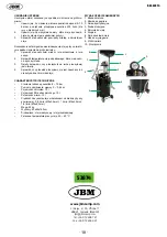
LISTADO DE PARTES
1. Recipiente de recogida
2. Vaso medidor
3. Tubo de bombeo
4. Tornillo de cierre
5. Depósito de aceite
6. Barra de soporte
7. Tubo de drenaje de aceite
8. Gancho de escape
9. Manómetro de vacío
10. Interruptor
ESPECIFICACIONES TÉCNICAS
•
Presión de trabajo: 8 ~ 10 bar
•
Nivel de vacío: 0 ~ 0.8 bar negativo
•
Capacidad del depósito: 70L
•
Capacidad del colador de recogida: 10L
•
Capacidad del vaso medidor: 10L
•
Velocidad de aspiración según diámetro de la varilla:
0.8L/min (Ø5x3.5mm); 1L/min (Ø6x4.5mm); 1.6 L/min
(Ø8x6.5mm)
•
Peso: 22kg
•
Dimensiones: 43x49x163cm
•
Tipo combustible: aceite de motor y de engranaje
•
Temperatura recomendada de trabajo del aceite: 40 ~
60ºC
2
7
1
3
4
5
6
8
9
10


