


Description and Operation
Base and Rover Setup
Base Station Configuration
46
www.javad.com
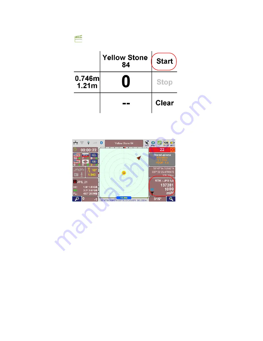
23. Press
Action
button
, to switch to
Command
screen and tap
Start
. To stop the base operation
tap
Stop
.
Figure 74. Command screen
24. Now base station is configured. Please do not move it!
25. In the
Action
screen ensure the base station is transmitting corrections:
Figure 75. Base station is transmitting corrections
26. To disable Base station, after finishing the work, tap
Settings
GNSS
Transmit Data (Base)
, and
set UHF modem format to None. Otherwise the base station operation will continue.