Operation
Before starting any welding activity ensure that you have
suitable eye protection and protective clothing. Also take
the necessary steps to protect any persons within the
area.
MMA
After connecting the welding leads as detailed you will need
to switch the power switch on the back panel to “ON”
Select MMA by switching to the MMA welding mode. There
is voltage output at both output terminals.
Set the amperage on the machine suitable for the electrode
being used. Please see below a guide to amperages
required. Ensure you check that you have the electrode
polarity correct.
TIG
Connect the TIG torch leads as detailed above. Ensure that a
suitable inert gas supply is connected.
Switch the MMA/TIG switch to TIG mode.
Open the gas valve of the cylinder, and adjust the gas
regulator to obtain the desired flow rate.
Switch the power switch on the back panel to “ON”, the
machine is started with the power LED on and the fan
working.
Press the torch trigger briefly, the solenoid valve will operate
and gas will flow.
Adjust the welding current according to the thickness of the
work piece to be welded. For a guide to welding parameters,
please refer to the tables below.
Hold the torch 2~4mm away from the work piece, and then
press the torch trigger. After arc is ignited, the HF discharge
will cease, the current will maintain the preset value, and
welding can be carried out.
After releasing the torch trigger, the current begins to down
slope automatically to the minimum value. Then, the arc
stops with gas kept flowing for the post-flow time, and
welding ends.
Adjust the downslope time potentiometer to change the time
according to the welding process requirements.
If the torch trigger is pressed again during the downslope
period, the welding current will immediately rise to the preset
value.
Operation of 2T/4T switch
2T:
Press the torch trigger, gas valve opens, and HF arc ignition
starts; Keep the torch 2~4mm away from the work piece to
ignite the arc. When the arc is established the HF stops, and
current rises to the preset value; Release the torch trigger,
current decreases to the minimum value, and then arc stops;
Gas keeps flowing for the post-flow time, and welding ends.
4T:
Press the torch trigger, gas valve opens, and HF arc ignition
starts; Keep the torch 2~4mm away from the work piece to
ignite the arc. When the arc is established the HF stops, and
current rises to the preset value; Release the torch trigger,
and welding continues at the preset current level. Press the
torch trigger again and release it, current begins to decrease
to the minimum value, and then arc stops; Gas keeps
flowing for the post-flow time, and welding ends.
For either the above modes, the HF discharge will remain on
in the case that the torch trigger is pressed but arc is not
ignited successfully. After arc is ignited, HF discharge will
end automatically. Whenever the arc is broken due to
external causes, HF discharge will restart automatically in
order to reignite the arc, and the HF discharge will not end
until either arc is ignited successfully or the torch trigger is
released.
Upslope time control
This function can be added upon customers’ requirements.
It is used to adjust the current increasing speed when the
current rises from the minimum value to the preset value
after arc is ignited successfully. If this function is not added,
the upslope time is 0.1s fixed.
TIG Tips
9
Electrode Diameter (mm)
Recommended Welding Current (A)
1.0
20~60
1.6
44~84
2.0
60~100
2.5
80~120
3.2
108~148
4.0
140~180
5.0
180~220
6.0
220~260
The welding current reference for different electrode diameters
The welding current reference for different electrode diameters
The welding current reference for different electrode diameters
The welding current reference for different electrode diameters
The welding current reference for different electrode diameters
Electrode diameter /mm
1.6
2.0
2.5
3.2
Welding current /A
25-40
40-60
50-80
100-130
Summary of Contents for TIG180
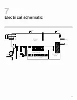
Page 14: ...Electrical schematic 7 13...
Page 15: ...Parts list 8 14...


