background image

37


CUT QUALITY


Dross 


The formation of dross on the bottom of the plate can be caused when cutting parameters such as          
speed, amperage, arc voltage, gas pressure/flow and type of gas are not correct for the metal type and 
thickness being cut. 


Most commonly, incorrect cutting speeds are to blame for excessive dross. High cutting speeds can 


results in high speed dross that can be very hard to remove without grinding. Low speed dross can be 


easily removed with a brush or chip hammer. 


Top edge rounding 


This is when the top edge of the cut face has eroded away and is not square which is created from the 
plasma cutting process. It is generally caused when cutting with excessive current or standoff distance. 


This can be a common occurrence when cutting thick materials.


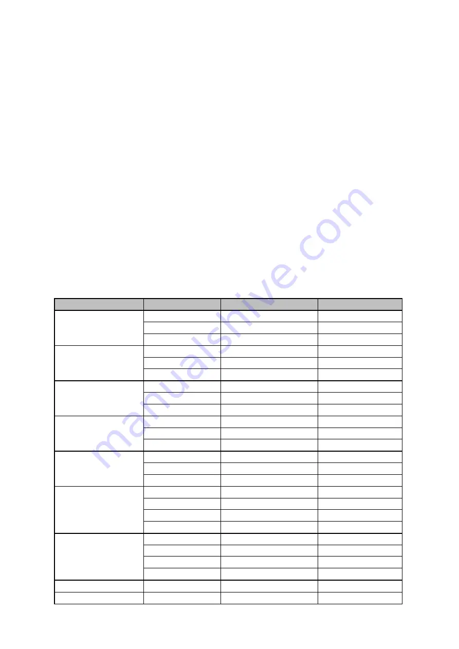
TYPICAL CUTTING SPEEDS


Cutting speeds can vary according to power source output, cutting table quality, material thickness along 
with material type being cut as well as the operators skill set. 


Speeds shown below are offered as a guide only for our Jasic hand cutting systems using compressed     
air, cutting mild steel material with the stated output currents ensuring that the cutting tip fitted matches 
the stated amperages. 


Note: The above chart is a guide as many factors can distort cutting chart figures when hand cutting.


Material Thickness


Amperage


Speed mm/m


Air Pressure


40


5000 

-

 6000


5 bar / 73psi


1mm


60


6200 

-

 7000


5 bar / 73psi


80


7200 

-

 8000


5 bar / 73psi


40


1800 

-

 2600


5 bar / 73psi


3mm


60


3200 

-

 4200


5 bar / 73psi


80


3800 

-

 4600


5 bar / 73psi


40


800 

-

 1100


5 bar / 73psi


6mm


60


1200 

-

 2000


5 bar / 73psi


80


1800 

-

 2500


5 bar / 73psi


40


200 

-

 300


5 bar / 73psi


12mm


60


400 

-

 650


5 bar / 73psi


80


650 

-

 820


5 bar / 73psi


60


400 

-

 500


5 bar / 73psi


15mm


80


450 

-

 540


5 bar / 73psi


100


750 

-

 880


5 bar / 73psi


60


280 

-

 340


5 bar / 73psi


20mm 


80


380 

-

 450


5 bar / 73psi


100


400 

-

 480


5 bar / 73psi


120


650 

-

 750


5 bar / 73psi


25mm 


80


180 

-

 210


5 bar / 73psi


100


200 

-

 240


5 bar / 73psi


120


300 

-

 380


5 bar / 73psi


160


400 

-

 480


5 bar / 73psi


30mm


160


320 

-

 400


5 bar / 73psi


45mm


160


230 

-

 350


5 bar / 73psi


Summary of Contents for EVO 2.0 EP-45

Page 1: ...1 ClearVision Optional TFT LCD screen included...

Page 2: ...rect information should you require assistance or spare parts Date purchased ________________________________________ From where ________________________________________ Serial number ________________...

Page 3: ...a 11 Product Overview 12 Technical Specifications 13 Description of EP 45 ClearVision Control Panel 14 Description of EP 45 Optional TFT LCD Control Panel 17 Description of Air Compressor 24 Installat...

Page 4: ...g should be regularly checked for damage and overheating Never use worn damaged under sized or poorly jointed cables Insulate yourself from work and earth using dry insulating mats or covers big enoug...

Page 5: ...cutting is taking place Wear suitable protective flame resistant clothing gloves and footwear Ensure adequate extraction and ventilation is in place prior to welding and cutting to protect users and...

Page 6: ...ding fume Ensure the welding zone is well ventilated and provision should be made for suitable local fume extraction system to be in place If ventilation is poor wear an approved airfed welding helmet...

Page 7: ...ated by high currents may affect the operation of pacemakers or electronically controlled medical equipment Wearers of vital electronic equipment should consult their physician before beginning any ar...

Page 8: ...permanent damage to your hearing Noise from cutting and welding equipment can damage hearing Always protect your ears from noise and wear approved and appropriate ear protection if noise levels are hi...

Page 9: ...AND UNPACKING Supplied within your new Jasic EVO product package will be the following items with each model Use care when unpacking the contents and ensure all items are present and not damaged If da...

Page 10: ...rance 15 I1max Rated maximum input current I1eff Maximum effective input current X Duty cycle The ratio of given duration time the full cycle time U0 No load voltage Open circuit voltage of secondary...

Page 11: ...tration The basic principle is that the arc is formed between the electrode and the work piece by forcing the plasma gas and the electrical arc through a small orifice within the copper tip This will...

Page 12: ...nufacturing power plant installation and construction industry metallurgy chemical engineering aerospace automobile and engineering vehicles manufacturing and construction facilities Jasic Cut EP 45 a...

Page 13: ...0V 15 Rated input current Imax A 115V 31 230V 23 115V 37 230V 27 Rated input power kVA 115V 3 6 230V 5 3 115V 10 230V 6 2 Cutting current range A 115V 20 30 230V 20 45 115V 20 30 230V 20 45 Rated oper...

Page 14: ...power cable 8 Air supply hose Dinse socket size is 15 25mm Rear view Jasic Cut EP 45 9 Machine carry handle 10 Input air regulator Adjustment knob 11 Input air regulator Pressure gauge 12 Input air re...

Page 15: ...lockwise increases the parameter value and rotating the adjusting knob counterclockwise decreases the parameter value When the adjusting knob is rotated the adjusted parameters are displayed in the pa...

Page 16: ...cutting mode selection button for 5 seconds when not cutting to restore factory mode 2 After 1 seconds the display window will count down from 3 After completion factory settings are restored If you...

Page 17: ...or Pressure gauge 12 Input air regulator Compressed air inlet 13 Machines ON OFF power switch 14 Rear panel with integrated cooling vents 15 Input power cable Control panel view Jasic Cut EP 45 16 Hom...

Page 18: ...creasing respectively Home Button Pressing the home button at any time will take you directly back to the home screen which is shown in the display screen image below Return Button The return button w...

Page 19: ...ease Note 2T 4T 4T is not available in grid cutting mode Cutting torch length and post flow time configuration Whether you are in continuous or mesh cutting modes you can enter the D tab which takes y...

Page 20: ...ttings icon shown left and then press the control dial You will then enter the settings screen from here you can scroll to information such as system information language choice unit selection factory...

Page 21: ...right The example shown is error E60 which is an over temperature error For a detailed list of error codes please see page 39 Configuration Settings Engineers mode From the settings screen rotate the...

Page 22: ...s of the machine On selecting the parameter reset option you can rotate the control dial to either accept or cancel the reset process pressing the control dial to accept will then reset all saved para...

Page 23: ...screen as shown below where you have easy access to some of the machines user instructions From here you can learn about the user interface control panel including the machine components and operation...

Page 24: ...ir outlet connection which connects the air hose to the power source regulator inlet see page 28 Please Note When using the EP 45SC via a portable transformer please ensure that you use a suitably siz...

Page 25: ...over Never use the machine on its side Most metals including stainless steel can give off toxic fume when welded or cut To protect the operator and others working in the area its important to have ad...

Page 26: ...offers only dry compressed air and is capable of delivering the volume of air that is required to run your plasma cutting machine to specification We recommend the minimum air supply requirements of...

Page 27: ...retaining cap is removed preventing machine operation Without such protection circuitry as previously mentioned the open circuit voltage could be as high as 350V DC at the torch head The torch head en...

Page 28: ...nding on which control panel your machine has activate the test air option which will then activate air purging to start the air flow through the machine and plasma torch refer to pages 15 or 20 for f...

Page 29: ...off the output You must release the torch trigger and press it again to re establish the pilot arc and keep cutting 4T continuous cutting When the main arc is extinguished due to lack of base material...

Page 30: ...igger to repress the trigger so in the case of cutting grid or perforated material we have the following option that should be used Perforated cutting mode Mesh cutting Perforated cutting This setting...

Page 31: ...orch away from the plate at a fixed height Also available are roller guides and circle cutting guide kits which can be very helpful in creating the cuts you want To begin cutting you would place the t...

Page 32: ...utting tip insulated shielded from the material being cut Using a drag shield cap allows you to rest the torch via the drag cap on the workpiece while maintaining an optimal 2 3mm standoff without tou...

Page 33: ...utting arc penetrates the work piece maintain your normal cutting height and the cutting process can then begin If the material being cut is thicker than 2mm the torch should be held at a 30 60 angle...

Page 34: ...09 Shielded Cutting Tip 0 9 30 40A Back Striking 10 12 51318C 10 Shielded Cutting Tip 1 0 40 50A Back Striking 10 14 60389 Retaining Cap 1 16 60389C Shield Cup Body 1 18 60432 Double Pointed Spacer f...

Page 35: ...much step on or press upon the cable to avoid restricting the air flow The cutting torch may be burned if the air flow is too low Keep the cutting cable away from sharp edges 8 When the work piece is...

Page 36: ...f guide or a cutting guide will help keep a consistent tip to work distance for best results Kerf width While plasma cutting a void is left behind which is called the kerf in the material being cut Be...

Page 37: ...with material type being cut as well as the operators skill set Speeds shown below are offered as a guide only for our Jasic hand cutting systems using compressed air cutting mild steel material with...

Page 38: ...e input cable plug and connections Check the ON OFF switch for function and continuity Primary power switch is on but the cooling fan does not work Check fan is not being blocked by debris Check fan f...

Page 39: ...in specification and the alarm persists contact an approved technician E32 Overvoltage protection The input mains voltage is too high Turn the machine off and back on again If the alarm continues chec...

Page 40: ...life time of consumables Low air pressure or low air flow or too Check for low air pressure to the plasma machine low flow be caused by a long air hose with a small internal diameter Ensure your comp...

Page 41: ...excessive wear on the cutting tip Do not overtighten the electrode when fitting a new set of consumables Over tightening may cause damage to the head thread the tip not to seat correctly Only use the...

Page 42: ...r the following steps every 1000 hours or 12 months of the air compressor running 1 Turn the rear panel air filter anticlockwise to open the outer cover 2 Replace the internal filter element 3 Install...

Page 43: ...tally compatible recycling facility Jasic has a relevant recycling system which is compliant and registered in the UK with the environment agency Our registration reference is WEEMM3813AA In order to...

Page 44: ...44 UKCA Declaration of Conformity...

Page 45: ...45 EC DECLARATION OF CONFORMITY...

Page 46: ...an incorrect or faulty mains supply Overloading during use Any modifications that are made to the product without the prior written consent Software errors due incorrect operation Any repairs that are...

Page 47: ...5 Pins function 1 2 115V AC 1 3 230V AC 4 Ground Compressor 4 Pin Plug Please Note Depending on region torch socket and torch wiring maybe different Please Note Depending on region torch socket and to...

Page 48: ..._________ _____________________________________ _____________________________________ _____________________________________ _____________________________________ _____________________________________...

Page 49: ..._________ _____________________________________ _____________________________________ _____________________________________ _____________________________________ _____________________________________...

Page 50: ...50...

Reviews: