Jasco PU-1580 Maintenance Manual Download Page 63


53 

 
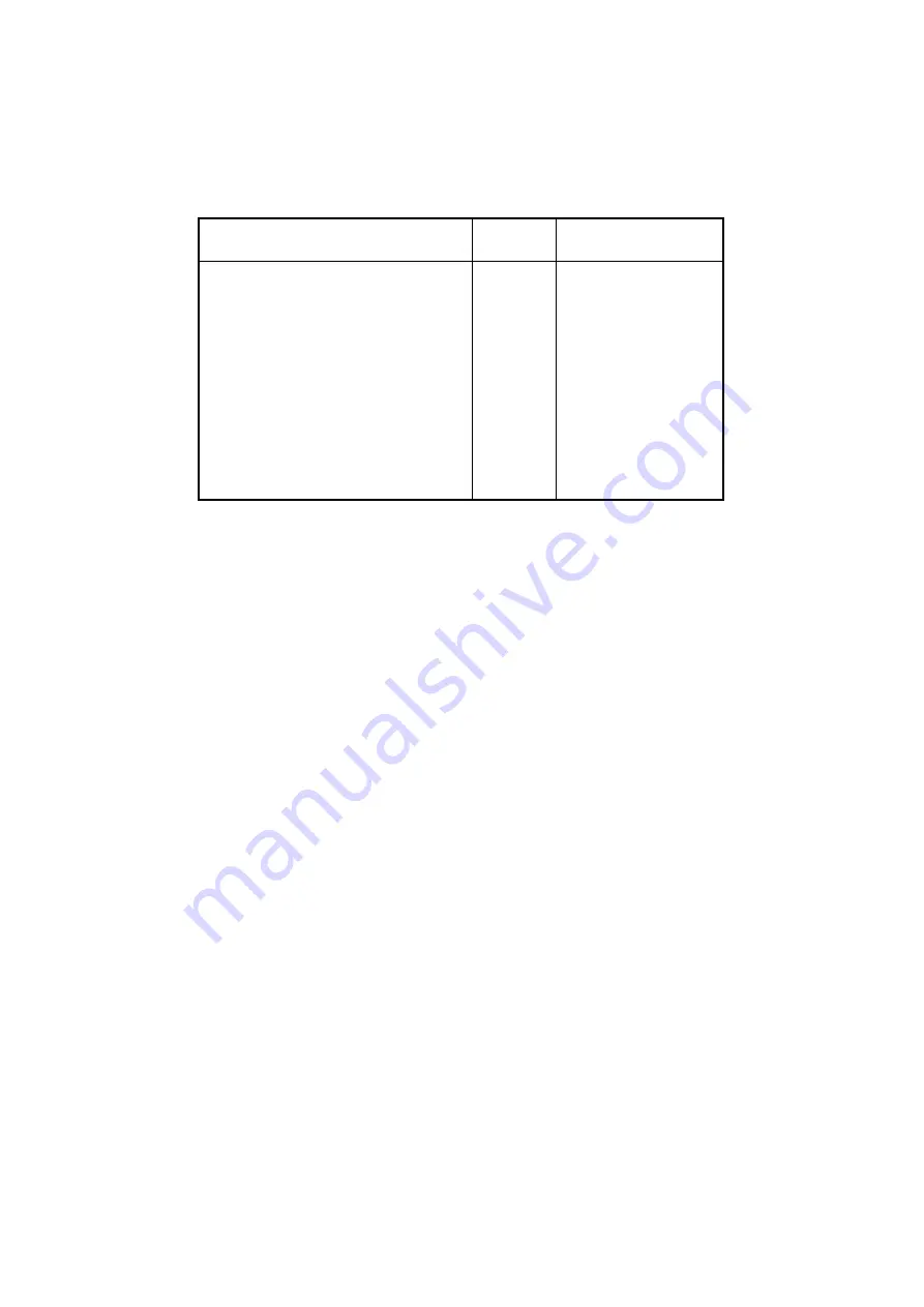
Table 5.1 lists the major consumable parts of the pump. 
 

Table 5.1  Consumable Parts List 


Part Name 

Order 

unit 

Reference 

diagram 

Inlet tube assembly 
Replacement plate filter 
Plunger seal (black) 
Line filter kit 
Plunger washing mechanism 
diaphragm 
purge valve needle 
Plunger 
Pump head assembly (delivery) 
Pump head assembly (modifier) 
Check valve assembly (IN) 
Check valve assembly (OUT) 

1 set 


2 sets 

10 


Fig. 5.14 
Fig. 5.14 

Fig. 5.9 

Fig. 5.13 
Fig. 5.20 


Fig. 5.22 
Fig. 5.25 

Fig. 5.3 
Fig. 5.3 

Fig. 5.16 
Fig. 5.16 


Summary of Contents for PU-1580

Page 1: ...P N 0302 0390B MODEL PU 1580 INTELLIGENT HPLC PUMP MAINTENANCE MANUAL...

Page 2: ...tentially hazardous situation which if not avoided could result in death or serious injury CAUTION A CAUTION indicates a potentially hazardous situation which if not avoided may result in minor or mod...

Page 3: ...ed Since water pipes are often constructed of non metallic materials e g polyvinyl chloride do not use these pipes for grounding purposes For safety reasons do not use gas pipes for grounding purposes...

Page 4: ...s instruction manual carefully and make sure that the contents are fully understood This manual should be easily accessible to the operator at all times during instrument operation When not using the...

Page 5: ...lower 5 Operate the instrument under an atmospheric pressure of 750 1060 hPa 6 Avoid strong magnetic fields and sources of high frequency waves The instrument may not function properly when near stron...

Page 6: ...es other than backup is prohibited y Transfer or authorization of the use of Jasco software to or by a third party is prohibited y Disclosure of confidential information related to Jasco software is p...

Page 7: ...ODIFICATION OR REPAIR BY PERSONS OTHER THAN AUTHORIZED JASCO PERSONNEL 4 USE OF PARTS OTHER THAN THOSE THAT ARE AUTHORIZED BY JASCO 5 INORDINATELY RAPID DETERIORATION DUE TO THE USE OF CORROSIVE SOLVE...

Page 8: ...TROUBLE UNDER PRESS errors 4 2 1 3 Large variations in operating pressure 5 2 2 Baseline problems 7 2 2 1 High baseline noise 8 2 2 2 Spike shaped baseline noise 8 2 2 3 Large baseline drift 9 2 2 4 P...

Page 9: ...acing the water with methanol 26 4 2 4 Notes on solvent replacement 26 4 3 Cleaning using an acid or alkaline solution 27 4 3 1 Conditions under which cleaning is required 27 4 3 2 Acid and alkaline s...

Page 10: ...erification 46 5 6 Purge valve needle and purge valve packing replacement 46 5 6 1 Purge valve needle replacement 47 5 6 2 Purge valve packing replacement 47 5 7 Plunger replacement 48 5 7 1 Plunger r...

Page 11: ...display When this happens various parameter settings will be erased and the default settings will be restored If a BACK UP ERROR occurs the procedures listed below should be followed 1 While holding...

Page 12: ...use If an error arises due to time variation in the pressure sensor zero the sensor using the zero adjustment trimmer then turn the power on again See Section 3 2 If the problem continues a malfunctio...

Page 13: ...ill appear on the display If the operating pressure is within an appropriate range decrease the minimum pressure P MIN setting If the operating pressure is lower than the normal range See Section 2 1...

Page 14: ...d or part s that may be clogged in the flow route Refer to the appropriate manual Line filter is clogged Operate the pump without anything connected to the outlet port If the pressure is 2 0 MPa or hi...

Page 15: ...2 4 1 If the leaking continues replace the plunger seal See Section 5 1 Inlet tube fitting is leaking Tighten the fitting See Section 2 4 6 Leak at downstream side of pump manual injector autosampler...

Page 16: ...ent degassing of the solvent Degas the solvent Inlet tube fitting is leaking Tighten the fitting See Section 2 4 6 Plunger seal is leaking Tighten the pump head securing screws See Section 2 4 1 If le...

Page 17: ...Modifier head Solvent selection valve knob or knob Purge valve knob Outlet port line filter inside Check valve assembly IN Pump head Outlet port Drain port Bottom view Head mount flange Figure 2 1 Pum...

Page 18: ...an extra mixer or damper to the pump Detector cell problems Bubbles Contamination Leakage Refer to the maintenance manual of the UV detector Decrease in the light intensity of the detector Light sourc...

Page 19: ...e maintenance manual of the UV detector Eluent contamination Lengthen the detector wavelength If the drift decreases there is a problem with the eluent Use a higher grade eluent Contamination of pump...

Page 20: ...tamination in sample injection section manual injector or autosampler Watch the ghost peaks while injecting eluent in the sample injection section Clean any equipment that has been determined to be co...

Page 21: ...re Is a breeze from the air conditioner striking the column Protect the column using thermal insulation 2 3 4 Poor reproducibility for peak areas or peak heights reproducibility for retention times is...

Page 22: ...mage to the instrument Inlet tube fitting leak see section 2 4 6 Outlet port leak see section 2 4 4 Purge valve leak see section 2 4 3 Check valve assembly leak see section 2 4 2 Plunger seal leak see...

Page 23: ...ION If the plunger washing mechanism is not used remove the washing water inlet and outlet ports on the bottom of the head mount flange Fig 2 2 shows the pump without the ports attached If the ports r...

Page 24: ...er than 20 cm as doing so may cause excessive torque to be applied to the check valve assembly causing the threads to become stripped Check valve assembly OUT Check valve assembly IN The check valve a...

Page 25: ...ide See Fig 2 5 Note Tightening the purge valve guide without the needle inserted may cause the packing to be overly compressed making reinsertion of the needle impossible If the leak persists replace...

Page 26: ...at to Do Deterioration of the diaphragm on the plunger washing mechanism Replace the diaphragm See Section 5 5 Leakage from the plunger seal When a plunger seal is leaking solvent will normally leak f...

Page 27: ...WARNING Chloroform and acetonitrile are hazardous to the human body and should not be used for the pressure test CAUTION Since salts in buffers may precipitate causing poor instrument performance do n...

Page 28: ...ned after 10 minutes and no external leakage is observable 6 If a leak is found refer to Section 2 4 to identify the appropriate method for dealing with the leak 3 2 Adjustment of Zero Pressure 3 2 1...

Page 29: ...10 0 0 0 P SENSOR SIG 2 0 MPa P SENSOR SIG 0 1 MPa C F 1 000 OFF 0 0 10 0 0 0 SHIFT PMAX 6 Monitor screen Pressure sensor signal screen Turn the PRESS ZERO ADJ trimmer on the back panel until the pres...

Page 30: ...w rate compensation screen Flow rate flashes Press 1 1 5 EDIT ENTER to input 115 PRESS COMP setting flashes Monitor screen Fluid delivery is not possible while this screen is displayed Note The settin...

Page 31: ...herefore when the FLOW COMP value is increased decreased by 1 the flow rate increases decreases by approximately 0 1 Input the FLOW COMP value calculated above Figure 3 5 Flow Rate Calibration Step 1...

Page 32: ...ow rate F Measured flow rate P Measured pressure MPa The above equation can be rearranged as follows F F P PRESS COMP 0 4 1 10 For example when P is 10 0 MPa and the PRESS COMP value is increased decr...

Page 33: ...rate to 10 ml min and the maximum pressure to 1 0 MPa Leave the purge valve open and repeatedly start and stop fluid delivery See Fig 4 1 Purge valve Drain tube Figure 4 1 Removing Air Bubbles via Hi...

Page 34: ...therefore should not be used to replace the solvent in the column or detector cell In the example described below a pump including the inlet tube contains a buffer solution containing salts referred...

Page 35: ...Verify that the solvent is flowing out of the drain tube without interruption 4 While continuing to pump lift the inlet tube out of the water take in 3 5 ml of air bubble and reinsert the inlet tube...

Page 36: ...ake sure that water continues to flow from the pump outlet port without interruption The solvent in the pump is thus replaced 4 2 3 Replacing the water with methanol In the procedures described in Sec...

Page 37: ...ntamination within the pump Problems traceable to deterioration of the pump head or contamination within the pump are listed below y Large pressure variation See Section 2 1 3 y High baseline noise Se...

Page 38: ...as detector cells quartz glass cells cannot withstand prolonged contact with alkaline solutions 4 3 3 Cleaning procedure A general outline of cleaning procedures is shown below Refer to Fig 4 5 for de...

Page 39: ...aline solution used to clean the pump will not corrode the components that come into contact with it However acid or alkaline solution will corrode other components such as the chassis LCD panel and e...

Page 40: ...tively harmless to both humans and the instrument must be selected for use during plunger seal replacement If organic solvents are currently being used replace these solvents with methanol If a buffer...

Page 41: ...g points when removing the pump head from the head mount flange 1 The pump head is divided into a delivery head and a modifier head Remove each head separately 2 Pull the pump heads straight out and d...

Page 42: ...Pump Head Tubing Attachment Removal Solvent selection valve Pump head Knob Head mount flange Plunger Allen bolt Bolt used to secure the pump head Allen wrench Purge valve knob delivery Pump head modif...

Page 43: ...33 Pull straight out Delivery head Figure 5 4 Diagram of Delivery Head Removal Plunger seal Small flathead screwdriver Figure 5 5 Plunger Seal Removal...

Page 44: ...34 Cross section Figure 5 6 Plunger Seal Attachment Hole...

Page 45: ...r seal into the seal pre forming tool Wait for two minutes press on the push up pole to extract the seal and install the seal immediately Note If the plunger seal cannot be smoothly inserted into the...

Page 46: ...e Remember the following when mounting the pump head onto the head mount flange 1 Press the head straight into the head mount flange and do not move it up down or left right 2 Take care not to jam or...

Page 47: ...edures for dealing with leaks from the plunger seal 5 2 Line filter replacement 5 2 1 Check for line filter clogs Pump solvent at 10 ml min while no tubing is connected to the pump outlet port and obs...

Page 48: ...the filter holder Remove the line filter Insert the new line filter Attach the filter retainer screw See Fig 5 13 Note When loosening the filter retainer screw use a wrench to hold the filter holder s...

Page 49: ...er replacement 5 3 1 How to check for inlet filter clogs Use a siphon to observe the flow of solvent in the inlet tube If solvent flows only intermittently the inlet filter is clogged and must be repl...

Page 50: ...rmless to both humans and the instrument must be selected for use during check valve assembly replacement If organic solvents are currently being used replace these solvents with methanol If a buffer...

Page 51: ...e loosening the check valve assembly If the bolts are loose the plungers may be damaged by loosening the check valve assembly 2 Loosen the bolts securing the pump head to their original tightness afte...

Page 52: ...ve assembly is difficult while the pump head is attached refer to Figs 5 2 5 4 and remove the pump head before replacing the check valve assembly When replacement of the check valve assembly is perfor...

Page 53: ...will unavoidably come into contact with fingers and hands In addition a leak may develop during the pressure test Therefore a solvent that is relatively harmless to both humans and the instrument must...

Page 54: ...ection 5 1 2 See Fig 5 3 Refer to Section 5 1 2 See Fig 5 3 Refer to Section 5 1 2 See Figs 5 3 and 5 4 Note Remember the following when removing the pump head from the head mount flange 1 The pump he...

Page 55: ...d Mount Flange Attachment Removal 5 5 3 Diaphragm replacement 1 Pull the diaphragm out from the plunger It may be easier to remove the diaphragm along with the spacer 2 Install the new diaphragm Note...

Page 56: ...t all parts and surfaces are facing the correct direction Note Any leakage from the plunger washing mechanism will drain through the drain port on the bottom panel Before operating the plunger washing...

Page 57: ...est reveals a leak see Section 2 4 3 which describes procedures for dealing with leaks from the purge valve The needle is secured to the knob by an Allen screw Inlet tube Needle Knob Guide Figure 5 22...

Page 58: ...ly harmless to both humans and the instrument must be selected for use during plunger replacement If organic solvents are currently being used replace these solvents with methanol If a buffer solution...

Page 59: ...it doesn t move The box wrench will move freely when a lock screw is loosened Be sure the wrench does not strike any of the plungers at this time 2 The disk may come out together with the plunger when...

Page 60: ...50 Plunger Box wrench Plunger guide Slider rod Lock screw Disk 1 2 Figure 5 25 Plunger Replacement Figure 5 26 Check After Plunger Attachment...

Page 61: ...5 mm Allen wrench to remove the knob from the solvent selection valve 2 Remove the tubing between the solvent selection valve and the pump head 3 Loosen the screw at the bottom left on the front pane...

Page 62: ...Valve Removel Attachment Stator Disk Coned disc springs Screw Ring Pin Valve axis Thrust bearing Bearing holder Knob Figure 5 29 Solvent Selection Valve Disassembly Diagram Pin Valve axis Disk Groove...

Page 63: ...lacement plate filter Plunger seal black Line filter kit Plunger washing mechanism diaphragm purge valve needle Plunger Pump head assembly delivery Pump head assembly modifier Check valve assembly IN...

Reviews: