background image


1

11

1. S

. Speci

pecifi

ficati

cation

ons

s

Display 

Display 

10.4 

10.4 inch 

inch TFT 

TFT LCD 

LCD (640 

(640 x 

x 480 

480 pixels)

pixels)

Frequency 

Frequency 

200kHz 

200kHz / 

/ 50kHz

50kHz

Echo 

Echo color 

color 

8 colors 

colors or 

or 8 

8 level 

level monochrome

monochrome

Digital 

Digital depth 

depth 

3 digit 

digit (0.0m 

(0.0m to 

to 99.9m 

99.9m : 

: 0.1m 

0.1m steps, 

steps, 100m 

100m over 

over : 

: 1m 

1m steps)

steps)

Ra

Rang

nge 

10

10m 

20

20m 

50

50m 

10

100m

0m

20

200m 

0m 

50

500m 

0m 

80

800m

0m

200kHz

200kHz

1.0m

1.0m

to

to

10m

10m

1.0m

1.0m

to

to

20m

20m

1.5m

1.5m

to

to

50m

50m

2.0m

2.0m

to

to

100m

100m

3.0m

3.0m

to

to

200m

200m

5.0m

5.0m

to

to

300m

300m

7.0m

7.0m

to

to

300m

300m

Sounding

Sounding
capability

capability

(Note1)

(Note1)

50kHz

50kHz

2.0m

2.0m

to

to

10m

10m

2.0m

2.0m

to

to

20m

20m

3.0m

3.0m

to

to

50m

50m

3.0m

3.0m

to

to

100m

100m

4.0m

4.0m

to

to

200m

200m

6.0m

6.0m

to

to

500m

500m

8.0m

8.0m

to

to

800m

800m

TX pulse

TX pulse
repetition rate

repetition rate

pulse  per

pulse  per

minute

minute

171

171

PPM

PPM

171

171

PPM

PPM

171

171

PPM

PPM

86

86

PPM

PPM

86

86

PPM

PPM

43

43

PPM

PPM

43

43

PPM

PPM

 Accuracy

 Accuracy

0.5m : 20m range, 5m : 

0.5m : 20m range, 5m : 200m range; or 2.5% of the indicated depth,

200m range; or 2.5% of the indicated depth,

whichever is greater 

whichever is greater 


Draft 

Draft adjust 

adjust 

0m 

0m to 

to 50m 

50m in 

in 0.1m 

0.1m steps

steps

Display 

Display mode 

mode 

Standard, 

Standard, History, 

History, Docking

Docking

Time range of

Time range of
echo display

echo display

5, 10, 20, 30min

5, 10, 20, 30min

 Auto function 

 Auto function 

Gain, Range

Gain, Range

 Alarm function 

 Alarm function 

Depth, Power fa

Depth, Power fail, System error

il, System error

Preview 

Preview function 

function 

12hour 

12hour or 

or 24hour

24hour

Transducers 

Transducers 

200kHz 

200kHz : 

: UT-200ND 

UT-200ND , 

,  50kHz 

50kHz : 

: UT-50MD

UT-50MD

100-115/200-230VAC

100-115/200-230VAC

±

±

15%, 50Hz/60Hz

15%, 50Hz/60Hz

±

±

5% 

5%  less 

less than 

than 50W

50W

Power supply

Power supply

24VDC (only use for power fail monitoring)

24VDC (only use for power fail monitoring)
Display unit : IPX5 jet proof

Display unit : IPX5 jet proof

Water proofing

Water proofing

Connection Box : IPX2 drip 

Connection Box : IPX2 drip proof

proof

Input 

Input nav. 

nav. data 

data 

IEC61162-1NMEA0183 

IEC61162-1NMEA0183  RMA, 

RMA, RMC, 

RMC, GGA, 

GGA, GLL, 

GLL, VTG

VTG, 

, ZDA

ZDA

Input 

Input ACK 

ACK signal 

signal 

IEC61162-1NMEA0183 

IEC61162-1NMEA0183  ALR

ALR

Input 

Input signals 

signals 

Power 

Power fail 

fail alarm 

alarm ACK:

ACK:

(Contact input: 12VDC 2.4mA, current 

(Contact input: 12VDC 2.4mA, current control: 12VDC 1.2mA)

control: 12VDC 1.2mA)

Depth alarm ACK, System 

Depth alarm ACK, System alarm ACK:

alarm ACK:

(Contact input: 5VDC 5mA, current control: 12VDC 1.2mA)

(Contact input: 5VDC 5mA, current control: 12VDC 1.2mA)

Output depth

Output depth
value data

value data

IEC61162-1 (NMEA0183 V1.5)

IEC61162-1 (NMEA0183 V1.5)
IEC61162-1 (NMEA0183 V2.3)

IEC61162-1 (NMEA0183 V2.3)

DBS, DBT, DBK

DBS, DBT, DBK
DPT

DPT

every 1 second

every 1 second
every 1 second

every 1 second

Output 

Output alarm 

alarm data 

data  IEC61162-1 

IEC61162-1 (NMEA0183) 

(NMEA0183) 

ALR 

ALR 

every 

every 1 

1 second

second

Output system

Output system
data

data
(IEC61162-1)

(IEC61162-1)

PJRCL

PJRCL
PJRCM (90)

PJRCM (90)
PJRCM (88, 89)

PJRCM (88, 89)

  
UTC

UTC
UTC

UTC

every 10 seconds

every 10 seconds
every 0 to 4 hours

every 0 to 4 hours
every 0 to 4 hours

every 0 to 4 hours

Output 

Output PC 

PC data 

data 

PJRCP

PJRCP

Output 

Output signals 

signals 

Power 

Power fail 

fail alarm, 

alarm, Depth 

Depth alarm, 

alarm, System 

System alarm:

alarm:

(Relay contact output: rated load 120VAC 10A, 30VDC 8A, NO/NC)

(Relay contact output: rated load 120VAC 10A, 30VDC 8A, NO/NC)

T

Temperature 

emperature 

–15°C 

–15°C to 

to +55°C 

+55°C / 

/ operating 

operating  –25°C 

–25°C to 

to +70°C 

+70°C / 

/ storage

storage

Humidity 

Humidity 

less 

less than 

than 93%RH 

93%RH under 

under +40°C 

+40°C condition 

condition (non-condens

(non-condensing)

ing)

Note1: Sounding capability would vary in frequency, gain setting, bottom shape, sea state,

Note1: Sounding capability would vary in frequency, gain setting, bottom shape, sea state,
vessel speed, etc.

vessel speed, etc.

1

11. 

1. Specification 

Specification  43

43

Summary of Contents for JFE-680

Page 1: ...JFE 680 JFE 680 E Ech cho S o Sou ound nde er r INSTRUCTION INSTRUCTION MANUAL MANUAL...

Page 2: ...4 4th th edition edition...

Page 3: ...e this equipment read this instruction manual thorough instruction manual thoroughly to ly to ensure correct and safe operation in accordance with the warning instructions and operation ensure correct...

Page 4: ...4 4th th edition edition General General Information Information ii ii...

Page 5: ...or operator or or physical damage to the equipment physical damage to the equipment Exa Example Pictogr mple Pictograms ams This mark is This mark is intended to alert the user intended to alert the u...

Page 6: ...place any vessels containing water or other Do not place any vessels containing water or other liquids liquids or me or metal tal objects objects on top on top of this of this equipment equipment If I...

Page 7: ...tact JRC or its agent There is a risk of There is a risk of file or electric shock if you continue to file or electric shock if you continue to use the use the equipmen equipment t If you notice smoke...

Page 8: ...oppling over resulting in injury the equipment falling or toppling over resulting in injury If it is cold If it is cold do not move the equipment suddenly into a do not move the equipment suddenly int...

Page 9: ...k Do not install the units on the place being poor Do not install the units on the place being poor ventilation ventilation Otherwise the set that is heated may cause a fire or Otherwise the set that...

Page 10: ...E Ext xte ern rna al l V View iew External External View View viii viii...

Page 11: ...Replacing the Fuses 5 2 Replacing the Fuses 6 6 Cons Consid ider er Inst Installat allatio ion n 7 Installation 7 Installation 7 1 Installing the Recorder Unit 7 1 Installing the Recorder Unit 7 2 In...

Page 12: ...atel separately by ea y by each ch European European NMEA0183 NMEA0183 NMEA NMEA stands stands for for the National the National Marine Marine Electroni Electronics cs Association Association NMEA0183...

Page 13: ...ck the past sounding informatio past sounding information n Dual frequency mode and two Dual frequency mode and two transducers are available in option requires an optional transducers are available i...

Page 14: ...00kHz Matching box Matching box secondary secondary AW AW 154F 50 154F 50 1 1 50kHz 50kHz NKF 341 NKF 341 1 1 200kHz 200kHz with with cable cable 20 30 40m 20 30 40m Transducer mounting Transducer mou...

Page 15: ...ternal dimensions of the JFE 680 The following shows the external dimensions of the JFE 680 1 E 1 Extern xternal Dimensio al Dimension of J n of JFE FE 680 680 2 Dimensions of AW 154F 50 AW 154F 50 Ma...

Page 16: ...ard equipment equipment Please re Please refer to fer to the separately supplied drawings if your the separately supplied drawings if your specifications are not standard specifications are not standa...

Page 17: ...1 1 5 S 5 System Conf ystem Configur iguration ation 1 1 Introduction Introduction 5 5...

Page 18: ...LR Clears Clears an an item item 7 7 PWR PANEL PWR PANEL Switches Switches the the equipment equipment power power on on and and off off adjusts adjusts the the brightness brightness of of the the pan...

Page 19: ...3 3 Disp Display lay 3 3 1 S 1 Standard mo tandard mode dual frequ de dual frequency ency 3 3 Display Display 7 7...

Page 20: ...3 3 2 H 2 Hist istory ory mode mode Keel height value Keel height value 3 3 Display Display 8 8...

Page 21: ...3 3 3 D 3 Dock ocking ing mode mode 3 3 Display Display 9 9...

Page 22: ...L key and use the arrow keys to adjust the control panel brightness The control panel illumination can not be turned fully off The control panel illumination can not be turned fully off it can only be...

Page 23: ...display the seabed otherwise you don t see the depth value Au Aut to omat matic ic Rang Range e In the Automatic range mode In the Automatic range mode the range scale the range scale is automaticall...

Page 24: ...the screen See figure below figure below Increase Increase sensitivity sensitivity Good Decrease Good Decrease sensitivity sensitivity Au Aut to oma mat ti ic c Gain Gain In the Automatic gain mode In...

Page 25: ...standard mode primary Single frequency standard mode secondary Dual frequency standard mode Single frequency history mode primary Single frequency history mode standard mode Single frequency history...

Page 26: ...Menu Tree 1 Menu Tree 1 4 4 Operation Operation 14 14...

Page 27: ...Menu Tree 2 Menu Tree 2 4 4 Operation Operation 15 15...

Page 28: ...item is item is highlighted on highlighted on the display the display In In the figure the figure at above at above DISPLAY DISPLAY is is selected selected When an item is When an item is highlighted...

Page 29: ...res it with the last three data three data Gain Gain Choose manual or automatic Choose manual or automatic Range Range Choose manual or automatic Choose manual or automatic Draft Draft Enter the de En...

Page 30: ...g characters 2 2 If due to bubbling etc it is If due to bubbling etc it is not possible to discriminate the sea bottom it is also not not possible to discriminate the sea bottom it is also not possibl...

Page 31: ...displays the the depth depth below below the the transducer transducer KEEL KEEL displays the displays the depth depth below below the the keel keel see see figure figure A A Primary Primary Enter th...

Page 32: ...d on the present the present screen screen HISTORY prints HISTORY prints all all the saved the saved data data graphically graphically LOG prints LOG prints a a specific period specific period of the...

Page 33: ...ly 4 Checksum result after each ASCII code of every character between S just after and 4 Checksum result after each ASCII code of every character between S just after and X just before is EXORed X jus...

Page 34: ...3 353 primary primary depth depth lost lost 354 354 secondary secondary depth depth lost lost 356 356 recording recording paper paper is is not not good good 357 357 printer printer connection connect...

Page 35: ...dow shown window shown above above The mode The mode switches each switches each time you time you press the press the up or up or downward arrow downward arrow key key When PRINTER is selected a prin...

Page 36: ...icing g See the li See the list of st of offices at the end of this manual offices at the end of this manual LCD C LCD Check heck SELF TEST SELF TEST CONTROL UNIT CONTROL UNIT LCD UNIT LCD UNIT KEY UN...

Page 37: ...f this manual this manual Print Printer T er Test est SELF TEST SELF TEST CONTROL UNIT CONTROL UNIT LCD UNIT LCD UNIT KEY UNIT KEY UNIT PRINTER TEST PRINTER TEST ALARM TEST ALARM TEST Display the Disp...

Page 38: ...Al Alarm arm lo log d g delet eletio ion n Deletes all the alarm log by pressing the ENT key Deletes all the alarm log by pressing the ENT key Line monitor Line monitor NAV DEPTH displays the Input o...

Page 39: ...the frequency setting me uency setting menu window nu window which said please do connection setting of transducers appears on the which said please do connection setting of transducers appears on th...

Page 40: ...will appear appear when when there there is is only only about about one one meter meter of of recording paper left on the roll recording paper left on the roll Handle the paper cutter carefully not...

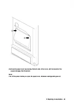
Page 41: ...ds of the cover with the tip end of the paper emerging from the printer paper emerging from the printer Note Note Turn off the power before you open the paper cover otherwise warring alarm goes off Tu...

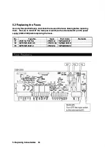
Page 42: ...side the side marked O marked O on the on the power power supply CQD 2083 before replacing the fuses supply CQD 2083 before replacing the fuses No No T Type ype No No Spec Spec Part Part Code Code Rem...

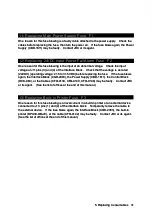
Page 43: ...blows again the Interface Block CGD 2083 the Power Supply CBD 1811 the Control Block again the Interface Block CGD 2083 the Power Supply CBD 1811 the Control Block OCK 963 or OCK 963 or the the Cable...

Page 44: ...re liable to be splashed with water 1 Where liable to be splashed with water 2 Where ventilation is poor 2 Where ventilation is poor Do not coat the Do not coat the part of the transducer that outputs...

Page 45: ...lure to observe this condition may result in the equipment falling or toppling over observe this condition may result in the equipment falling or toppling over resulting in injury resulting in injury...

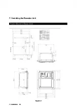
Page 46: ...7 7 1 Insta 1 Installin lling t g the Re he Recor corder Unit der Unit Flush Mounted E Flush Mounted Equip quipment ment Figure 3 1 Figure 3 1 7 7 Installati Installation on 34 34...

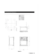
Page 47: ...Wall Mounted Equipment Wall Mounted Equipment Figure 3 2 Figure 3 2 7 7 Installation Installation 35 35...

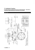
Page 48: ...rated be strated below are low are for the s for the standard tandard equipment equipment Please re Please refer to fer to the separately supplied drawings if your the separately supplied drawings if...

Page 49: ...NKF 345 NKF 345 7 7 Installation Installation 37 37...

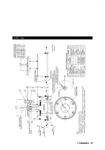
Page 50: ...NKF 392C NKF 392C 7 7 Installati Installation on 38 38...

Page 51: ...rs etc contact any other connectors etc 2 Casings must be grounded securely to the ship s hull using copper plates 2 Casings must be grounded securely to the ship s hull using copper plates 3 The exte...

Page 52: ...ck the transducer No echo sounding picture No echo sounding picture Frequency Frequency setting setting is is wrong wrong Check Check the the frequency frequency setting setting Low Low sensitivity se...

Page 53: ...Submitted Name type No Name type No month and year of month and year of manufacture and serial number manufacture and serial number Nature of fault in as Nature of fault in as much detail as possible...

Page 54: ...e dispose of this equipment following the guidelines of the local body governing the Please dispose of this equipment following the guidelines of the local body governing the location at which the equ...

Page 55: ...4VDC only use for power fail monitoring 24VDC only use for power fail monitoring Display unit IPX5 jet proof Display unit IPX5 jet proof Water proofing Water proofing Connection Box IPX2 drip Connecti...

Page 56: ...ndi dix x Noise Noise Bubble Bubble Noise Noise Bubble Bubble Interrupt Interruption ion Interference Noise from other ship Interference Noise from other ship Plankton layer Plankton layer Appendix Ap...

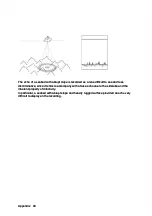
Page 57: ...or surface of hull bottom or surface of sea and again reflected at the sea and again reflected at the seabed toward the transducer seabed toward the transducer Such multiple Such multiple recording of...

Page 58: ...ultrasonic wave In case of a soft seabed made of mud seaweed etc they poorly reflect an ultrasonic wave to result in thin recording of the seabed with short trail to result in thin recording of the se...

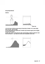
Page 59: ...turn of seabed may sometimes appear which is slightly In case of flat seabed thin second return of seabed may sometimes appear which is slightly below the actual below the actual seabed seabed In eith...

Page 60: ...false tends to accompany with a false echo due to the echo due to the sidelobe and the sidelobe and the inherent property of directivity inherent property of directivity In particular a seabed with ab...

Page 61: ......

Page 62: ......
Reviews: