background image

5

Rahmenschweisslehre RSL 3025

Frame welding gauge RSL 3025

12/2020

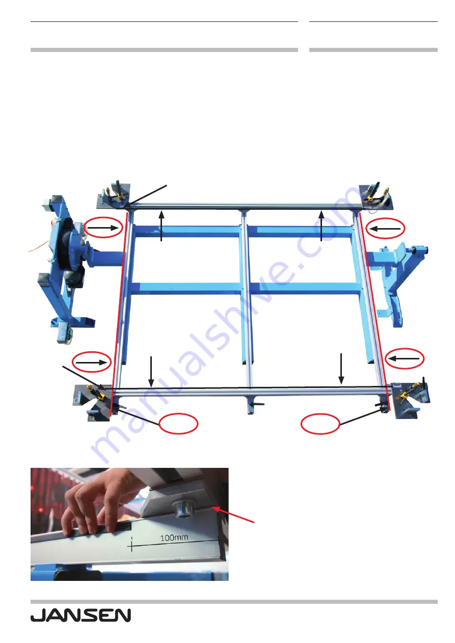
Anbringen der Magnetbänder
Attaching the magnetic strips

Vor dem Ankleben des Magnetbandes ist darauf zu achten, 
dass für die Breite die kürzeren und für die Länge die 
längeren Bänder verwendet werden.
Für die Breite ist das Abstandsmass von 

100 mm

 zum 

Profilende zu beachten (siehe nachfolgende Bilder). Beim 
Ankleben darauf achten, dass der Magnetstreifen jeweils 

aussenseitig

 parallel an die Abstufung vom Profil anliegend 

befestigt wird.

Before adhering the magnetic strip, ensure that the shorter 
strips are used for the width and the longer strips are used 
for the length.
For the width, the clearance of 

100 mm

 to the profile end 

should be observed (see images below). When adhering 
the magnetic strips ensure that each of them is attached 
on the 

outside

 parallel to the raised edge of the profile.

Abstufung vom Profil
Raised edge of profile

100 mm

300 mm

300 mm

100 mm

Summary of Contents for RSL 3025

Page 1: ...Bedienungsanleitung Digitalanzeige RSL 3025 Nachr stung der digitalen Positionsanzeige 499 551 Operating instructions for digital display RSL 3025 Retrofitting the digital position display 499 551...

Page 2: ...Frame welding gauge RSL 3025 12 2020 Anleitung zum Einbau der optionalen Digitalanzeige f r die Jansen Rahmenschweisslehre RSL 3025 Instructions on installing the optional digital display for the Jans...

Page 3: ...Magnetb nder 1 Attaching the magnetic strips 2 Montieren der digitalen Positionsanzeige 2 Installing the digital position display 3 Einstellen des Offsetwertes der digitalen Positionsanzeige 3 Setting...

Page 4: ...diese vorg ngig mit einem handels blichen Reiniger seitlich auf der ganzen L nge gereinigt und ent fettet werden siehe rote Pfeile im nachfolgenden Bild 1 Attaching the magnetic strips To ensure that...

Page 5: ...r Beim Ankleben darauf achten dass der Magnetstreifen jeweils aussenseitig parallel an die Abstufung vom Profil anliegend befestigt wird Before adhering the magnetic strip ensure that the shorter stri...

Page 6: ...eim Ankleben darauf achten dass der Magnetstreifen jeweils innenseitig parallel an die Abstufung vom Profil anliegend befestigt wird For the length the clearance of 300 mm to the profile end should be...

Page 7: ...the corner marked with a red circle Lesekopf rot f r Positionsanzeige gem ss Bild an den vorhandenen Gewindel cher festschrauben Dabei die Aluminiumplatte unter den Lesekopf legen Wichtig Der Lesekopf...

Page 8: ...ngdistanzh lsen fixieren 1 Messingdistanzh lse 2 Befestigungsschrauben Attach the digital display to the recess provided in the clamping corner with two screws and brass spacer sleeve 1 Brass spacer s...

Page 9: ...uminiumplatte unter den Lesekopf legen Wichtig Der Lesekopf darf nicht am Positionsband streifen Auf einen Abstand zwischen 0 1 bis 0 5 mm achten Screw reading head red for position display tightly in...

Page 10: ...ndicator to be installed now is intended to display the width Die Digitalanzeige bei welcher der Lesekopf sowie die An zeige an der Halterung bereits vormontiert ist muss von unten her mit zwei Schrau...

Page 11: ...t kann die Taste losgelassen werden Press and hold the P button on the digital display for 5 seconds to enter programming mode As soon as the display shows AuFL you can release the button Distanz zwis...

Page 12: ...ired decimal point Then save the entered value with the button To exit programming mode navigate to the end of the pa rameter list using the P button the current position is shown or do not touch any...

Page 13: ...der Taste auf allen vier digitalen Anzeigen referenzieren Hierbei wird das beim Kapitel Einstellen des Offsetwertes der Digital Messuhr gespeicherte Mass bernommen 4 Referencing the corner stop plates...

Page 14: ...Jansen AG Steel Systems Industriestrasse 34 9463 Oberriet Schweiz jansen com D1003948 DE EN I Steel Systems I 12 2020 I nderungen vorbehalten...

Reviews: